EP0376506A1 - Mail handling machine with mis-sealed envelope detector - Google Patents
Mail handling machine with mis-sealed envelope detector Download PDFInfo
- Publication number
- EP0376506A1 EP0376506A1 EP89312581A EP89312581A EP0376506A1 EP 0376506 A1 EP0376506 A1 EP 0376506A1 EP 89312581 A EP89312581 A EP 89312581A EP 89312581 A EP89312581 A EP 89312581A EP 0376506 A1 EP0376506 A1 EP 0376506A1
- Authority
- EP
- European Patent Office
- Prior art keywords
- envelope
- sealed
- handling machine
- flap
- blade
- Prior art date
- Legal status (The legal status is an assumption and is not a legal conclusion. Google has not performed a legal analysis and makes no representation as to the accuracy of the status listed.)
- Granted
Links
Images


Classifications
-
- B—PERFORMING OPERATIONS; TRANSPORTING
- B43—WRITING OR DRAWING IMPLEMENTS; BUREAU ACCESSORIES
- B43M—BUREAU ACCESSORIES NOT OTHERWISE PROVIDED FOR
- B43M5/00—Devices for closing envelopes
- B43M5/04—Devices for closing envelopes automatic
- B43M5/042—Devices for closing envelopes automatic for envelopes with only one flap
-
- B—PERFORMING OPERATIONS; TRANSPORTING
- B65—CONVEYING; PACKING; STORING; HANDLING THIN OR FILAMENTARY MATERIAL
- B65H—HANDLING THIN OR FILAMENTARY MATERIAL, e.g. SHEETS, WEBS, CABLES
- B65H43/00—Use of control, checking, or safety devices, e.g. automatic devices comprising an element for sensing a variable
- B65H43/04—Use of control, checking, or safety devices, e.g. automatic devices comprising an element for sensing a variable detecting, or responding to, presence of faulty articles
-
- Y—GENERAL TAGGING OF NEW TECHNOLOGICAL DEVELOPMENTS; GENERAL TAGGING OF CROSS-SECTIONAL TECHNOLOGIES SPANNING OVER SEVERAL SECTIONS OF THE IPC; TECHNICAL SUBJECTS COVERED BY FORMER USPC CROSS-REFERENCE ART COLLECTIONS [XRACs] AND DIGESTS
- Y10—TECHNICAL SUBJECTS COVERED BY FORMER USPC
- Y10S—TECHNICAL SUBJECTS COVERED BY FORMER USPC CROSS-REFERENCE ART COLLECTIONS [XRACs] AND DIGESTS
- Y10S209/00—Classifying, separating, and assorting solids
- Y10S209/90—Sorting flat-type mail
Definitions
- This invention relates to mail handling machines, and in particular to mail handling machines for processing mixed mail including sealed and unsealed envelopes.
- Co-pending European application, EP Attorney Reference C.444, USSN 291,438 describes a mail machine for high speed processing of mixed mail, which includes unsealed as well as sealed envelopes.
- the mail flow in such a machine typically begins at a hopper where the incoming mail to be processed is stacked.
- the main flow path continues through a singulator, which separates individual mail pieces from the stack for serial processing.
- the envelopes are caused to flow along the main path through a moistener which moistens the glue on the flaps of the unsealed envelopes and then seals the envelopes, and thereafter along the main path to a weigher and printer including a postage meter.
- the machine is intended to handle mixed mail, by which is meant unsealed envelopes with the flaps open in the position for moistening, unsealed envelopes with the flap closed and which has to be opened by the machine to the moistening position, and already-sealed envelopes.
- mis-sealed envelopes that is, envelopes in which the sealed edge, instead of lying flat, may protrude outwardly or display other undesired anomalous leading edge states. If allowed to continue along the main flow path, such mis-sealed envelopes may jam the machine.
- a mail handling maching having means for serially transporting along a main path sealed and unsealed close-flapped and opern-flapped envelopes and means the main path for moistening the flaps of the unsealed envelopes, which machine includes means upstream of the moistening means for detecting mis-sealed envelopes.
- the mis-sealed envelope detector is combined with a flap stripper, the device which moves the flap of an unsealed envelope from its closed to its open position.
- a biased pivotable member is positioned in the main flow path.
- the pivotable member is shaped to perform the flap stripping function, and is biased so that it does not move during a normal flap stripping operation.
- the biasing is such that the pivotable member is forced out of the flow path by an oncoming mis-sealed envelope. This movement can be detected and used temporarily to slow the processing or to inform an operator that potentially jamming envelopes are in the main flow path and precautions should be taken.
- the mis-sealed envelope detector is associated with apparatus located downstream of the singulator but upstream of the moistener and which functions to position the flap of the unsealed envelopes at an orientation ready for the moistening operation.
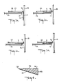
- Fig. 1 schematically illustrates examples of mixed mail that the apparatus of the invention can handle.
- Fig. 1a depicts an unsealed envelope 10 whose flap 11 is open. In this position, water can be sprayed onto the flap glue line 12 and the flap sub sequently sealed.
- Commonly-owned U.S. Patent No. 3,911,862 illustrates apparatus with this capability.
- the envelope is being transported across a deck 13 contacted by the bottom surface of the envelope, and along a registration side wall 15 contacted by the fold edge 16 of the envelope.
- the flap in this downward position typically rides in a slot 17 between the registration wall and the deck edge.
- the deck 13 and wall 15 have been shown spaced from the envelope for clarity.
- Fig. 1b shows a properly sealed envelope 10, with the flap 11 glued down tight to the envelope body. In this case, the flap will contact the deck 13.
- Fig. 1c shows a sealed envelope 10 that was improperly sealed, typically because the flap bulges as shown at 18.
- Fig. 1d shows an unsealed envelope 10 with the flap in a closed position.
- the machine processes the four kinds of mail shown differently.
- a sensor detects the flap in the slot and primes the moistener to operate.
- the envelope in Fig. 1b should encounter no obstacles and pass through the moistener and sealer without being processed.
- the envelope in Fig. 1c will likely jam the machine modules downstream; therefore it must be detected and handled specially.
- the envelope in Fig. 1d must have its flap stripped open and pushed into the slot 17, so it appears as depicted in Fig. 1a and is processed the same way.
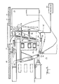
- Fig. 2 shows the setting of the preferred example of this apparatus of the invention in the mail handling machine.
- Envelopes 10 are transported across a deck 13 by conventional transport means 20.
- the flap stripping takes place where indicated by 21.
- the envelope continues along the machine deck where the profile of the open flap is taken to control a moistener 22 whose spray nozzle 23 is positioned under the deck 13, and the envelope then proceeds downstream to the sealer.
- the moistener and sealer only become activated when an envelope appears whose flap is located in the slot 17. Properly sealed envelopes flow right through stations 21 and 22 without interruption.
- Fig. 3 shows in greater detail the construction of station 21, a key feature of which is a pivotably-mounted, airfoil-shaped blade 24 which has a wedge-like cross-section, depicted in Fig. 4.
- the blade 24 has a sharp front edge 25, flat top sections 26 in line with the deck 13, which optionally may be separated by cut-out areas 25, and an end 27 that curves downstream.
- the back side 28 is flat except for a downstream extension 29 which is used to support and position the blade 24.
- the blade 24 has an upstream transverse arm extension 31 which is pivotably mounted 32 on the machine deck 13.
- the blade 24 can be made of plastic or other material. Extending downward from and affixed to the blade is a magnet 33.
- a Hall-effect device 34 is mounted on the machine bed.
- a torsion spring 36 (Fig. 5) biases the blade 24 towards a closed position as shown in Fig. 3, in which magnet 33 is adjacent the Hall-effect detec tor 34. The latter acts as a sensor to detect position and/or movement of the blade 24.
- a biased finger 37 is mounted on the registration wall 15 and pushes the mail's flap edge, if unsealed, down toward the deck to pucker the flap from the envelope so that it may be stripped for moistening.
- a similar biased finger 38 also helps keep the envelope down against the deck 13 which continues downstream driven by the roller drive 39.
- Fig. 5 illustrates the motion of the blade 24.
- the blade In solid lines it is shown in its closed position, with magnet 33 in one of its two states.
- the blade When hit by a mis-sealed envelope, the blade will rotate CW to the partially open position 24′ shown in phantom, typically about 10°. However, an operator can manually rotate the blade about 90° CW to a completely open position where it is completely out of the mail path flow. In both the partially and completely open positions, the sensor 34 is switched to its opposite state.
- the blade 24 profile is shaped such that when the unsealed envelope shown in Fig. 1d reaches this station, as illustrated in Fig. 6, the finger end 37 pushes down the envelope leading edge 40 as it crosses a gap 41 between a deck edge 42 and the front edge 25 of the blade. This action causes the flap 11 to separate or open wider, and it is forced under the angled bottom surface 44 on the blade, the main body of the envelope continuing over the top surface 26.
- the gap 41 opens (Fig. 5) to the slot 17 upstream, and the slot 17 downstream.
- the curved shaped at the end 27 of the blade (Fig. 5) assists in achieving this desired flap position.
- the shaped structure 47 which is affixed to the deck just downstream of the blade 24 also assists in directing the flap into the slot 27, the flap passing under a curved wall 48 extending down from the structure 47.
- the blade 24 remains in its closed position.
- the spring 36 tension is chosen so that the force required to strip open the flap does not exceed the spring tension. Thus, no signal is sent from the sensor 34 to the machine controller, depicted at 50.
- Figs. 9 and 10 illustrate what happens when a properly sealed envelope as depicted in Fig. 1b comes along. In this case, no bulge is present and the sealed flapped edge as well as the envelope body pass smoothly over the top surface of the blade 24 without activating it. In other words, the blade 24 remains in its closed position.
- the controller When the sensor has been activated and sends a signal to the controller, several ways exist to handle the situation. The simplest is for the controller to stop the machine, and signal the operator that a mis-sealed envelope is encountered, in which case the operator would manually swing the blade 24 out of the way, and reach in and remove the mis-sealed envelope. Alternatively, when the mis-sealed envelope is intercepted by the blade 24 and becomes stuck, causing the blade to rotate and activating the sensor, the controller can be programmed to slow down the forward drives 45 for the envelope for several microseconds.
- the envelope can become unstuck and continue downstream, thus allowing the blade to swing CCW to its closed position, thereby informing the controller that the temporary jam has ended and allowing processing to continue. If the envelope can succeed in passing the structure 47, it is not likely to cause a jam downstream in the machine.
- a preferred way of handling the situation when the stripper blade opens is by means of suitable programming of the micro controller 50.
- three possible events can occur: (1) the envelope passes straight through without budging the blade 24 which remains in its home or closed position; (2) the envelope has a small bulge which opens the blade 24 but the envelope doesn't get stuck and continues downstream in which case the spring-biased blade 24 returns to its closed position; this is acceptable; and (3) the envelope gets stuck on the blade and doesn't proceed downstream.
- the microcontroller 50 which controls the drives as explained in the copending application (C.444) is readily programmed to handle intelligently the three possibilities enumerated above.
- One suitable program in pseudocode is illustrated in Fig. 11, which will be best understood also with reference to Fig. 3.
- the upstream envelope 10 before it reaches the flap stripping station 21 and while still under control of the takeaway nip of the singulator (the so-called post-nip position), is temporarily stopped or paused by the controller awaiting completion of the processing of the preceding downstream envelope.
- the program commences with an initial state designated CASE_0, in which it waits for an envelope to reach the post-nip or pause position.
- event (3) If it times-out and the blade 24 has not yet returned to its closed position, then event (3) is assumed, the controller shuts down the drives, the machine stops, and the user is informed of a jam and the steps to take to clear the jam, essentially to remove the stuck envelope. Otherwise, in the ELSE statement, if the blade 24 has returned before the counter timed out, then everything is OK, the envelope is now at the downstream station and control returns to CASE_0.
- CASE_3 is provided to cover the possibility of a flap only sealed at the rear part of the envelope, but not at the front part.
- the open part of the flap at the front will not move the blade 24, and as mentioned above, the envelope is then advanced normally and control falls through to CASE_3. If, then, the arm 24 is suddenly opened, because the rear sealed part of the flap catches the arm, then the machine is stopped and the user informed to take anti-jam action; otherwise, if the arm remains closed then everything is OK and control returns to the initial state CASE_0.
- the flap When the flap is stripped open into the downstream slot 17, it need not occupy a vertical position.
- the flap is forced up against an angled wall which houses the flap profiler in a position that allows the moistener underneath to spray the flap glue line.
- Aims of the invention as particularly disclosed and illustrated herein are:- to provide apparatus for distinguishing between properly sealed and improperly or mis-sealed envelopes; to provide a mail handling machining for processing mixed mail and having for detecting and differently processing mis-sealed flapped envelopes; and to provide a mailing machine in which mixed mail is serially processed and provided with means for temporarily slowing mis-sealed mail and for taking special measures for handling such mis-sealed mail.
Abstract
Description
- This invention relates to mail handling machines, and in particular to mail handling machines for processing mixed mail including sealed and unsealed envelopes.
- Co-pending European application, EP Attorney Reference C.444, USSN 291,438 describes a mail machine for high speed processing of mixed mail, which includes unsealed as well as sealed envelopes. The mail flow in such a machine typically begins at a hopper where the incoming mail to be processed is stacked. The main flow path continues through a singulator, which separates individual mail pieces from the stack for serial processing. Following the singulator, the envelopes are caused to flow along the main path through a moistener which moistens the glue on the flaps of the unsealed envelopes and then seals the envelopes, and thereafter along the main path to a weigher and printer including a postage meter. The machine is intended to handle mixed mail, by which is meant unsealed envelopes with the flaps open in the position for moistening, unsealed envelopes with the flap closed and which has to be opened by the machine to the moistening position, and already-sealed envelopes.
- In this environment, it is important to detect the presence of mis-sealed envelopes, that is, envelopes in which the sealed edge, instead of lying flat, may protrude outwardly or display other undesired anomalous leading edge states. If allowed to continue along the main flow path, such mis-sealed envelopes may jam the machine.
- A mail handling maching having means for serially transporting along a main path sealed and unsealed close-flapped and opern-flapped envelopes and means the main path for moistening the flaps of the unsealed envelopes, which machine includes means upstream of the moistening means for detecting mis-sealed envelopes. In one aspect of the invention, there is positioning in the main flow path of the mixed mail being processed a means for distinguishing between properly sealed, unsealed-with-flap-closed, unsealed-with-flap-open, and mis-sealed envelopes. It is one of the surprising results of this aspect of the invention that essentially mechanical means can be provided to perform this function.
- In accordance with another aspect of the invention, the mis-sealed envelope detector is combined with a flap stripper, the device which moves the flap of an unsealed envelope from its closed to its open position. By integrating the two functions, less space is used in the machine, and the overall length of the machine can be reduced.
- In a preferred embodiment, a biased pivotable member is positioned in the main flow path. The pivotable member is shaped to perform the flap stripping function, and is biased so that it does not move during a normal flap stripping operation. However, the biasing is such that the pivotable member is forced out of the flow path by an oncoming mis-sealed envelope. This movement can be detected and used temporarily to slow the processing or to inform an operator that potentially jamming envelopes are in the main flow path and precautions should be taken.
- In accordance with still another aspect of the invention, the mis-sealed envelope detector is associated with apparatus located downstream of the singulator but upstream of the moistener and which functions to position the flap of the unsealed envelopes at an orientation ready for the moistening operation. Thus, both the treatment of the unsealed and properly sealed envelopes and the detection of the mis-sealed envelopes take place at the same station. This conserves space and speeds up the processing.
- A preferred embodiment of the invention will now be described in connection with the accompanying drawings, wherein:
- Fig. 1a-1d are end view schematics of the different species of mixed mail required to be handled by the machine;
- Fig. 2 is a perspective view of one form of the apparatus according to the invention, in relation to the downstream moistening module;
- Fig. 3 is a perspective view from the top of the flap stripper and mis-sealed flap detector station of the invention shown in Fig. 2;
- Fig. 4 is a cross-sectional view of the flap-stripping blade taken along the line 4-4 of Fig. 5;
- Fig. 5 is a top view of the station illustrated in Fig. 3;
- Fig. 6 is a side view from the front of the station illustrated in Fig. 3 during a flap-stripping operation;
- Figs. 7-10 are perspective views showing operation of the mis-sealed flap detector when mis-sealed and properly sealed envelopes are driven past;
- Fig. 11 lists an example of pseudocode for a programmable controller to handle the envelope flow through the flap detector station.
- Fig. 1 schematically illustrates examples of mixed mail that the apparatus of the invention can handle. Fig. 1a depicts an
unsealed envelope 10 whoseflap 11 is open. In this position, water can be sprayed onto the flap glue line 12 and the flap sub sequently sealed. Commonly-owned U.S. Patent No. 3,911,862 illustrates apparatus with this capability. In such a machine, typically the envelope is being transported across adeck 13 contacted by the bottom surface of the envelope, and along aregistration side wall 15 contacted by thefold edge 16 of the envelope. The flap in this downward position typically rides in aslot 17 between the registration wall and the deck edge. Thedeck 13 andwall 15 have been shown spaced from the envelope for clarity. - Fig. 1b shows a properly sealed
envelope 10, with theflap 11 glued down tight to the envelope body. In this case, the flap will contact thedeck 13. - Fig. 1c shows a sealed
envelope 10 that was improperly sealed, typically because the flap bulges as shown at 18. - Fig. 1d shows an
unsealed envelope 10 with the flap in a closed position. - The machine processes the four kinds of mail shown differently. When the envelope in Fig. 1a comes through, a sensor detects the flap in the slot and primes the moistener to operate. The envelope in Fig. 1b should encounter no obstacles and pass through the moistener and sealer without being processed. The envelope in Fig. 1c will likely jam the machine modules downstream; therefore it must be detected and handled specially. The envelope in Fig. 1d must have its flap stripped open and pushed into the
slot 17, so it appears as depicted in Fig. 1a and is processed the same way. - Fig. 2 shows the setting of the preferred example of this apparatus of the invention in the mail handling machine.
Envelopes 10 are transported across adeck 13 by conventional transport means 20. The flap stripping takes place where indicated by 21. Thereafter the envelope continues along the machine deck where the profile of the open flap is taken to control a moistener 22 whosespray nozzle 23 is positioned under thedeck 13, and the envelope then proceeds downstream to the sealer. The moistener and sealer only become activated when an envelope appears whose flap is located in theslot 17. Properly sealed envelopes flow right throughstations - Fig. 3 shows in greater detail the construction of
station 21, a key feature of which is a pivotably-mounted, airfoil-shaped blade 24 which has a wedge-like cross-section, depicted in Fig. 4. Theblade 24 has a sharpfront edge 25,flat top sections 26 in line with thedeck 13, which optionally may be separated by cut-outareas 25, and anend 27 that curves downstream. Theback side 28 is flat except for adownstream extension 29 which is used to support and position theblade 24. - The
blade 24 has an upstreamtransverse arm extension 31 which is pivotably mounted 32 on themachine deck 13. Theblade 24 can be made of plastic or other material. Extending downward from and affixed to the blade is amagnet 33. A Hall-effect device 34 is mounted on the machine bed. A torsion spring 36 (Fig. 5) biases theblade 24 towards a closed position as shown in Fig. 3, in whichmagnet 33 is adjacent the Hall-effect detec tor 34. The latter acts as a sensor to detect position and/or movement of theblade 24. Abiased finger 37 is mounted on theregistration wall 15 and pushes the mail's flap edge, if unsealed, down toward the deck to pucker the flap from the envelope so that it may be stripped for moistening. A similarbiased finger 38 also helps keep the envelope down against thedeck 13 which continues downstream driven by theroller drive 39. - Fig. 5 illustrates the motion of the
blade 24. In solid lines it is shown in its closed position, withmagnet 33 in one of its two states. When hit by a mis-sealed envelope, the blade will rotate CW to the partiallyopen position 24′ shown in phantom, typically about 10°. However, an operator can manually rotate the blade about 90° CW to a completely open position where it is completely out of the mail path flow. In both the partially and completely open positions, thesensor 34 is switched to its opposite state. - The
blade 24 profile is shaped such that when the unsealed envelope shown in Fig. 1d reaches this station, as illustrated in Fig. 6, thefinger end 37 pushes down theenvelope leading edge 40 as it crosses agap 41 between adeck edge 42 and thefront edge 25 of the blade. This action causes theflap 11 to separate or open wider, and it is forced under theangled bottom surface 44 on the blade, the main body of the envelope continuing over thetop surface 26. Thegap 41 opens (Fig. 5) to theslot 17 upstream, and theslot 17 downstream. The continued forward movement of theenvelope 10, by thedrive 45, therefore causes theflap 11 to follow thebottom surface 44 and is gradually forced into a generally vertical position and enters thedownstream slot 17, positioned to undergo moistening. The curved shaped at theend 27 of the blade (Fig. 5) assists in achieving this desired flap position. The shapedstructure 47 which is affixed to the deck just downstream of theblade 24 also assists in directing the flap into theslot 27, the flap passing under acurved wall 48 extending down from thestructure 47. During this entire flap-stripping operation, theblade 24 remains in its closed position. Thespring 36 tension is chosen so that the force required to strip open the flap does not exceed the spring tension. Thus, no signal is sent from thesensor 34 to the machine controller, depicted at 50. - Now, when a mis-sealed envelope as depicted in Fig. 1c comes along, as shown in Fig. 7, the
bulge 18 which tends to open due to the pressure offinger 37, will be intercepted by theblade edge 25, which will try to strip open theflap 11. This is shown in Fig. 8. Since the latter is sealed, instead the spring tension is overcome and the arm starts to swing away as shown by the arrow. After about a 10° rotation, thesensor 34 will switch states and send a signal to thecontroller 50. While it is possible to substitute an electrical switch for themagnetic detector 34, the typical electrical switch will actuate as soon as thearm 24 begins to rotate. By using a magnetic switch, the sensor doesn't switch states until the magnet has moved at least a short distance away. This avoids undesired switch actions due to small movements of theblade 24 when no mis-sealed envelope is present. - Figs. 9 and 10 illustrate what happens when a properly sealed envelope as depicted in Fig. 1b comes along. In this case, no bulge is present and the sealed flapped edge as well as the envelope body pass smoothly over the top surface of the
blade 24 without activating it. In other words, theblade 24 remains in its closed position. - When the sensor has been activated and sends a signal to the controller, several ways exist to handle the situation. The simplest is for the controller to stop the machine, and signal the operator that a mis-sealed envelope is encountered, in which case the operator would manually swing the
blade 24 out of the way, and reach in and remove the mis-sealed envelope. Alternatively, when the mis-sealed envelope is intercepted by theblade 24 and becomes stuck, causing the blade to rotate and activating the sensor, the controller can be programmed to slow down the forward drives 45 for the envelope for several microseconds. If thebulge 18 is not too large, then the envelope can become unstuck and continue downstream, thus allowing the blade to swing CCW to its closed position, thereby informing the controller that the temporary jam has ended and allowing processing to continue. If the envelope can succeed in passing thestructure 47, it is not likely to cause a jam downstream in the machine. - A preferred way of handling the situation when the stripper blade opens is by means of suitable programming of the
micro controller 50. In particular, three possible events can occur: (1) the envelope passes straight through without budging theblade 24 which remains in its home or closed position; (2) the envelope has a small bulge which opens theblade 24 but the envelope doesn't get stuck and continues downstream in which case the spring-biasedblade 24 returns to its closed position; this is acceptable; and (3) the envelope gets stuck on the blade and doesn't proceed downstream. - The
microcontroller 50 which controls the drives as explained in the copending application (C.444) is readily programmed to handle intelligently the three possibilities enumerated above. One suitable program in pseudocode is illustrated in Fig. 11, which will be best understood also with reference to Fig. 3. In the normal operation of the machine, assuming perfect envelope flow, theupstream envelope 10, before it reaches theflap stripping station 21 and while still under control of the takeaway nip of the singulator (the so-called post-nip position), is temporarily stopped or paused by the controller awaiting completion of the processing of the preceding downstream envelope. The program commences with an initial state designated CASE_0, in which it waits for an envelope to reach the post-nip or pause position. Due to the dimensioning of the machine, when the envelope is in the post-nip position, the envelope's leading edge will have reached theblade 24. Two possibilities exist. The envelope edge has not budged theblade 24, or it has. Returning now to the program, when an envelope reaches the post-nip posi tion, detected by a sensor, then the program flow drop down to state CASE_1. If the blade has not moved, i.e., theblade 24 or arm as referred to in Fig. 11 is in its home or closed position, then everything is OK and the drives are activated to move the envelope to thenext station 13, and program control drops through to CASE_3. - While still in CASE_1, if, on the other hand, the blade has budged and moved to its open position, then the ELSE statement tells the controller to activate the drives with a slower-than-normal velocity profile while starting a time (TIME-OUT) to count down from an assigned value X based on how long it should take for the
blade 24 to return to its closed position if event (2) has occurred, a minor bulge that is acceptable and will allow the envelope to proceed downstream and undergo normal processing, rather than event (3). The reduced velocity, in effect, provides increased time to allow the machine to recover, if it can, from what may be only a temporary glitch, without a significant sacrifice in throughput. Program control then passes to CASE_2 to distinguish these two events (2) and (3) wherein the counter state is tested. If it times-out and theblade 24 has not yet returned to its closed position, then event (3) is assumed, the controller shuts down the drives, the machine stops, and the user is informed of a jam and the steps to take to clear the jam, essentially to remove the stuck envelope. Otherwise, in the ELSE statement, if theblade 24 has returned before the counter timed out, then everything is OK, the envelope is now at the downstream station and control returns to CASE_0. - Finally, CASE_3 is provided to cover the possibility of a flap only sealed at the rear part of the envelope, but not at the front part. In this situation, while at state CASE_1, the open part of the flap at the front will not move the
blade 24, and as mentioned above, the envelope is then advanced normally and control falls through to CASE_3. If, then, thearm 24 is suddenly opened, because the rear sealed part of the flap catches the arm, then the machine is stopped and the user informed to take anti-jam action; otherwise, if the arm remains closed then everything is OK and control returns to the initial state CASE_0. - It will be clear from the foregoing to those skilled in this art that other programs can readily be devised to perform the above-described functions of distinguishing the three events mentioned. Moreover, if desired, hard-wired logic circuitry can instead be provided to perform the same functions.
- When the flap is stripped open into the
downstream slot 17, it need not occupy a vertical position. Preferably the flap is forced up against an angled wall which houses the flap profiler in a position that allows the moistener underneath to spray the flap glue line. - By combining the flap-stripping and mis-sealed envelope detecting functions at a single station within the mail-handling machine, space is conserved and subsequent jamming of the machine is avoided. This allows the machine to handle a large variety of mixed mail, and to be operated at higher speeds to increase throughput of properly sealed envelopes.
- Aims of the invention as particularly disclosed and illustrated herein are:- to provide apparatus for distinguishing between properly sealed and improperly or mis-sealed envelopes; to provide a mail handling machining for processing mixed mail and having for detecting and differently processing mis-sealed flapped envelopes; and to provide a mailing machine in which mixed mail is serially processed and provided with means for temporarily slowing mis-sealed mail and for taking special measures for handling such mis-sealed mail.
Claims (20)
Applications Claiming Priority (2)
| Application Number | Priority Date | Filing Date | Title |
|---|---|---|---|
| US291099 | 1988-12-28 | ||
| US07/291,099 US4955483A (en) | 1988-12-28 | 1988-12-28 | Mail handling machine with mis-sealed envelope detector |
Publications (2)
| Publication Number | Publication Date |
|---|---|
| EP0376506A1 true EP0376506A1 (en) | 1990-07-04 |
| EP0376506B1 EP0376506B1 (en) | 1993-11-10 |
Family
ID=23118833
Family Applications (1)
| Application Number | Title | Priority Date | Filing Date |
|---|---|---|---|
| EP89312581A Expired - Lifetime EP0376506B1 (en) | 1988-12-28 | 1989-12-01 | Mail handling machine with mis-sealed envelope detector |
Country Status (5)
| Country | Link |
|---|---|
| US (1) | US4955483A (en) |
| EP (1) | EP0376506B1 (en) |
| AU (1) | AU627248B2 (en) |
| CA (1) | CA2004115C (en) |
| DE (1) | DE68910663T2 (en) |
Cited By (4)
| Publication number | Priority date | Publication date | Assignee | Title |
|---|---|---|---|---|
| EP0487324A1 (en) * | 1990-11-21 | 1992-05-27 | Pitney Bowes Inc. | Mailing machine including mailpiece guiding apparatus |
| GB2318340A (en) * | 1996-10-18 | 1998-04-22 | Pitney Bowes Inc | Envelope closing apparatus with ejection of incorrectly-filled envelopes |
| FR2833885A1 (en) * | 2001-12-21 | 2003-06-27 | Neopost Ind | UNIVERSAL DEVICE FOR WETTING FLAPS |
| EP1440816A1 (en) * | 2003-01-23 | 2004-07-28 | Neopost Industrie | Separator for supply unit of a franking machine |
Families Citing this family (10)
| Publication number | Priority date | Publication date | Assignee | Title |
|---|---|---|---|---|
| US5138816A (en) * | 1991-08-12 | 1992-08-18 | Pitney Bowes Inc. | Mail handling machine with improved envelope flap opening means |
| US5524995A (en) * | 1994-11-14 | 1996-06-11 | Pitney Bowes, Inc. | Apparatus and method for detecting the position of envelopes in a mailing machine |
| US5809752A (en) * | 1996-12-27 | 1998-09-22 | Pitney Bowes Inc. | Sealing device for a mailing machine |
| US6041569A (en) * | 1997-07-11 | 2000-03-28 | Pitney Bowes Inc. | Mailing machine having envelope closing and sealing device |
| US6196392B1 (en) | 1997-12-23 | 2001-03-06 | Profold, Inc. | Method and apparatus for feeding and tabbing intermixed pieces of mail |
| US6609662B2 (en) | 2000-02-01 | 2003-08-26 | Profold, Inc. | Debit card having secure scratch-off label strip with releasable layer and method of applying same |
| US6199757B1 (en) | 2000-02-01 | 2001-03-13 | Profold, Inc. | Debit card having scratch-off label strip and method of applying same |
| US6578874B1 (en) | 2000-03-13 | 2003-06-17 | Profold, Inc. | Method for correcting articles of mail and article of mail produced thereby |
| US6766626B2 (en) | 2002-10-15 | 2004-07-27 | Pitney Bowes Inc. | Floating stripping skis for mailing machine |
| US8783094B2 (en) * | 2011-12-27 | 2014-07-22 | Fmr Llc | Envelope seal verification system and method |
Citations (1)
| Publication number | Priority date | Publication date | Assignee | Title |
|---|---|---|---|---|
| US1799820A (en) * | 1926-05-08 | 1931-04-07 | Bircher Co Inc | Envelope-sealing machine |
Family Cites Families (11)
| Publication number | Priority date | Publication date | Assignee | Title |
|---|---|---|---|---|
| US2028277A (en) * | 1934-07-17 | 1936-01-21 | Nat Postal Meter Company | Envelope flap opening and moistening device |
| US2944511A (en) * | 1958-04-21 | 1960-07-12 | Pitney Bowes Inc | Letter flap moistener |
| DE2113316C3 (en) * | 1971-03-19 | 1975-07-24 | Focke & Pfuhl Verpackungsautomaten, Sonderkonstruktionen, 3090 Verden | Device for checking the presence of a sealing strip on packs |
| US3910007A (en) * | 1973-04-26 | 1975-10-07 | Baeuerle Gmbh Mathias | Device for opening the flaps of envelopes |
| US3901797A (en) * | 1974-06-05 | 1975-08-26 | Pitney Bowes Inc | Automatic continuous mail handling system |
| US3939063A (en) * | 1974-10-10 | 1976-02-17 | Gerber Products Company | Loose flap detector and case ejector system for wrap-around paperboard cartons |
| US4330061A (en) * | 1980-05-15 | 1982-05-18 | Hauni-Werke Korber & Co. Kg. | Method and apparatus for detecting and segregating defective commodities from a series of discrete commodities |
| US4428794A (en) * | 1982-08-04 | 1984-01-31 | Xerox Corporation | Apparatus for sealing envelopes |
| US4450037A (en) * | 1983-06-22 | 1984-05-22 | Pitney Bowes Inc. | Envelope flap sealing device |
| JPS60172629A (en) * | 1984-02-15 | 1985-09-06 | シルバー精工株式会社 | Automatic sealing machine |
| FR2598975B1 (en) * | 1986-05-26 | 1991-10-25 | Smh Alcatel | DEVICE FOR OPENING ENVELOPES. |
-
1988
- 1988-12-28 US US07/291,099 patent/US4955483A/en not_active Expired - Lifetime
-
1989
- 1989-11-29 CA CA002004115A patent/CA2004115C/en not_active Expired - Fee Related
- 1989-12-01 EP EP89312581A patent/EP0376506B1/en not_active Expired - Lifetime
- 1989-12-01 DE DE89312581T patent/DE68910663T2/en not_active Expired - Fee Related
- 1989-12-07 AU AU45994/89A patent/AU627248B2/en not_active Ceased
Patent Citations (1)
| Publication number | Priority date | Publication date | Assignee | Title |
|---|---|---|---|---|
| US1799820A (en) * | 1926-05-08 | 1931-04-07 | Bircher Co Inc | Envelope-sealing machine |
Cited By (9)
| Publication number | Priority date | Publication date | Assignee | Title |
|---|---|---|---|---|
| EP0487324A1 (en) * | 1990-11-21 | 1992-05-27 | Pitney Bowes Inc. | Mailing machine including mailpiece guiding apparatus |
| GB2318340A (en) * | 1996-10-18 | 1998-04-22 | Pitney Bowes Inc | Envelope closing apparatus with ejection of incorrectly-filled envelopes |
| GB2318340B (en) * | 1996-10-18 | 2000-02-16 | Pitney Bowes Inc | Envelope closing apparatus |
| FR2833885A1 (en) * | 2001-12-21 | 2003-06-27 | Neopost Ind | UNIVERSAL DEVICE FOR WETTING FLAPS |
| EP1321311A3 (en) * | 2001-12-21 | 2003-11-26 | Neopost Industrie | Universal moistening device for flaps |
| US6893534B2 (en) | 2001-12-21 | 2005-05-17 | Neopost Industrie | Universal device for moistening envelope flaps |
| EP1440816A1 (en) * | 2003-01-23 | 2004-07-28 | Neopost Industrie | Separator for supply unit of a franking machine |
| FR2850323A1 (en) * | 2003-01-23 | 2004-07-30 | Neopost Ind | SEPARATOR DEVICE FOR FEEDING MACHINE FEEDER |
| US7442276B2 (en) | 2003-01-23 | 2008-10-28 | Neopost Technologies | Separator device for franking machine feeder |
Also Published As
| Publication number | Publication date |
|---|---|
| DE68910663D1 (en) | 1993-12-16 |
| CA2004115C (en) | 2002-01-22 |
| DE68910663T2 (en) | 1994-03-03 |
| CA2004115A1 (en) | 1990-06-28 |
| US4955483A (en) | 1990-09-11 |
| AU627248B2 (en) | 1992-08-20 |
| AU4599489A (en) | 1990-07-05 |
| EP0376506B1 (en) | 1993-11-10 |
Similar Documents
| Publication | Publication Date | Title |
|---|---|---|
| EP0376506B1 (en) | Mail handling machine with mis-sealed envelope detector | |
| US4971686A (en) | Mail handling machine with mis-sealed envelope detector | |
| US4798040A (en) | Insertion machine | |
| EP0943460B1 (en) | Envelope inserting apparatus | |
| US4119194A (en) | System and apparatus for the orientation and bidirectional feed of indicia bearing mail | |
| CA1300575C (en) | Envelope opening apparatus | |
| US5722221A (en) | Envelope opening apparatus | |
| CA2327043C (en) | Method and apparatus for detecting proper mailpiece position and feeding | |
| JPS6336554B2 (en) | ||
| IE55736B1 (en) | Mail handling device | |
| US6481712B1 (en) | Apparatus for preventing lead to trail edge collision of mailpieces in a sorter | |
| US5729954A (en) | Envelope flap opener apparatus | |
| US5265731A (en) | Job separator | |
| US5642598A (en) | Collation feeding mechanism for envelope inserting machine | |
| US20020140162A1 (en) | Stacker | |
| US5249794A (en) | Feed device for a sorting machine for sorting flat objects such as postal items | |
| US5832702A (en) | Motion control profile to improve reliability of inserter during insertion | |
| US4911422A (en) | Inserter reject station | |
| US4939887A (en) | Insertion machine | |
| EP0528623A1 (en) | Mail handling machine with improved envelope flap opening means | |
| EP0537978B1 (en) | Method and apparatus for sorting cut sheet form components into stacks | |
| US3877693A (en) | Distributor assembly for sheet sorting device | |
| US6568671B1 (en) | Method and system for determining if a mailpiece has properly exited from a mailing machine | |
| EP1676647B1 (en) | Over the raceway divert device, system and method for diverting suspect documents | |
| CA2182335C (en) | Envelope offset apparatus |
Legal Events
| Date | Code | Title | Description |
|---|---|---|---|
| PUAI | Public reference made under article 153(3) epc to a published international application that has entered the european phase |
Free format text: ORIGINAL CODE: 0009012 |
|
| AK | Designated contracting states |
Kind code of ref document: A1 Designated state(s): CH DE FR GB LI |
|
| 17P | Request for examination filed |
Effective date: 19901205 |
|
| 17Q | First examination report despatched |
Effective date: 19920929 |
|
| GRAA | (expected) grant |
Free format text: ORIGINAL CODE: 0009210 |
|
| AK | Designated contracting states |
Kind code of ref document: B1 Designated state(s): CH DE FR GB LI |
|
| REF | Corresponds to: |
Ref document number: 68910663 Country of ref document: DE Date of ref document: 19931216 |
|
| ET | Fr: translation filed | ||
| PLBI | Opposition filed |
Free format text: ORIGINAL CODE: 0009260 |
|
| 26 | Opposition filed |
Opponent name: FRANCOTYP- POSTALIA GMBH Effective date: 19940810 |
|
| PLAB | Opposition data, opponent's data or that of the opponent's representative modified |
Free format text: ORIGINAL CODE: 0009299OPPO |
|
| R26 | Opposition filed (corrected) |
Opponent name: FRANCOTYP-POSTALIA GMBH Effective date: 19940810 |
|
| PLBN | Opposition rejected |
Free format text: ORIGINAL CODE: 0009273 |
|
| STAA | Information on the status of an ep patent application or granted ep patent |
Free format text: STATUS: OPPOSITION REJECTED |
|
| 27O | Opposition rejected |
Effective date: 19951113 |
|
| REG | Reference to a national code |
Ref country code: GB Ref legal event code: IF02 |
|
| PGFP | Annual fee paid to national office [announced via postgrant information from national office to epo] |
Ref country code: GB Payment date: 20031126 Year of fee payment: 15 |
|
| PGFP | Annual fee paid to national office [announced via postgrant information from national office to epo] |
Ref country code: FR Payment date: 20031218 Year of fee payment: 15 |
|
| PGFP | Annual fee paid to national office [announced via postgrant information from national office to epo] |
Ref country code: CH Payment date: 20031223 Year of fee payment: 15 |
|
| PGFP | Annual fee paid to national office [announced via postgrant information from national office to epo] |
Ref country code: DE Payment date: 20040202 Year of fee payment: 15 |
|
| PG25 | Lapsed in a contracting state [announced via postgrant information from national office to epo] |
Ref country code: GB Free format text: LAPSE BECAUSE OF NON-PAYMENT OF DUE FEES Effective date: 20041201 |
|
| PG25 | Lapsed in a contracting state [announced via postgrant information from national office to epo] |
Ref country code: LI Free format text: LAPSE BECAUSE OF NON-PAYMENT OF DUE FEES Effective date: 20041231 Ref country code: CH Free format text: LAPSE BECAUSE OF NON-PAYMENT OF DUE FEES Effective date: 20041231 |
|
| PG25 | Lapsed in a contracting state [announced via postgrant information from national office to epo] |
Ref country code: DE Free format text: LAPSE BECAUSE OF NON-PAYMENT OF DUE FEES Effective date: 20050701 |
|
| GBPC | Gb: european patent ceased through non-payment of renewal fee |
Effective date: 20041201 |
|
| REG | Reference to a national code |
Ref country code: CH Ref legal event code: PL |
|
| PG25 | Lapsed in a contracting state [announced via postgrant information from national office to epo] |
Ref country code: FR Free format text: LAPSE BECAUSE OF NON-PAYMENT OF DUE FEES Effective date: 20050831 |
|
| REG | Reference to a national code |
Ref country code: FR Ref legal event code: ST |
|
| PLAB | Opposition data, opponent's data or that of the opponent's representative modified |
Free format text: ORIGINAL CODE: 0009299OPPO |