EP0876773B1 - Method, apparatus and hair extension product thereof - Google Patents
Method, apparatus and hair extension product thereof Download PDFInfo
- Publication number
- EP0876773B1 EP0876773B1 EP19980830205 EP98830205A EP0876773B1 EP 0876773 B1 EP0876773 B1 EP 0876773B1 EP 19980830205 EP19980830205 EP 19980830205 EP 98830205 A EP98830205 A EP 98830205A EP 0876773 B1 EP0876773 B1 EP 0876773B1
- Authority
- EP
- European Patent Office
- Prior art keywords
- moulding
- concave
- tool
- thermoplastic resin
- hair
- Prior art date
- Legal status (The legal status is an assumption and is not a legal conclusion. Google has not performed a legal analysis and makes no representation as to the accuracy of the status listed.)
- Expired - Lifetime
Links
Images

Classifications
-
- A—HUMAN NECESSITIES
- A41—WEARING APPAREL
- A41G—ARTIFICIAL FLOWERS; WIGS; MASKS; FEATHERS
- A41G5/00—Hair pieces, inserts, rolls, pads, or the like; Toupées
- A41G5/004—Hair pieces
- A41G5/0053—Fastening thereof
- A41G5/008—Fastening thereof by adhesives
-
- A—HUMAN NECESSITIES
- A41—WEARING APPAREL
- A41G—ARTIFICIAL FLOWERS; WIGS; MASKS; FEATHERS
- A41G5/00—Hair pieces, inserts, rolls, pads, or the like; Toupées
- A41G5/004—Hair pieces
- A41G5/0086—Applicators or tools for applying hair extensions
Definitions
- the present invention relates to a method of preparing hair extensions for creating hairstyles, a tool for the said method and an extension prepared by this method.
- a number of currently fashionable hairstyles require the attachment to the person's natural hair of hair extensions in, for example, the form of ponytails, plaits and the like. These extensions are attached to the natural hair and removed from it as the wearer requires.
- these known hair extensions are prepared by bonding natural hair or artificial hair (the latter will also be called hair in this text), or the like, together at one end with a small quantity of adhesive substance, usually a thermoplastic resin.
- a small quantity of adhesive substance usually a thermoplastic resin.
- This operation is performed by holding the lock of hair in the fingers of one hand; the other hand then applies a drop of heated, and therefore fluid, resin onto the ends of the hair.
- the hairs are then worked and twisted between the fingers to form, with the consequent immediate hardening of the resin once it has cooled, a cylinder comprising resin and hair, similar to a slubbing or roving.
- the hair extension is heated with a suitable tool on the roving as prepared above and joined to the natural hair, or indeed to a wig, where desired.
- US-A-4 982 748 shows such a kind of tool, comprising a pair of tip members which are adapted for mounting on arm members of a conventional curling iron.
- the tip members include pointed portions and opposing flat surfaces which facilitate the application of heat to a wrapped four-piece braid of both filaments and normal hair to be extended.
- the fingers tend to stick to the hair extension and the result is an irregular cylinder.
- the object of the present invention is therefore to overcome the abovementioned disadvantages.
- the present invention relates to a method of preparing hair extensions for creating hairstyles, in which a quantity of thermoplastic resin is applied in the fluid state to one end of a lock of natural or artificial hairs in order to bond them together to form a hair extension, forming a concave shell, similar in form to a fingernail, which is suitable for the subsequent accommodation in the abovementioned concavity of a lock of the wearer's own hair to which the hair extension is to be attached.
- the method according to the invention is such as to comply with work safety standards.
- a method of preparing hair extensions comprises the following steps:
- the invention additionally provides, for the preparation of hair extensions for creating hairstyles, a tool, such as a compressive moulding tool comprising a concave half or die and a convex half or punch, preferably made of a non-stick material with respect to the thermoplastic resin, in which the halves of the moulding tool are movable towards each other to compress the end of the lock of hair in contact with the thermoplastic resin, and away from each other after compression and hardening, for moulding the thermoplastic resin into a concave shell similar in form to a fingernail.
- a tool such as a compressive moulding tool comprising a concave half or die and a convex half or punch, preferably made of a non-stick material with respect to the thermoplastic resin, in which the halves of the moulding tool are movable towards each other to compress the end of the lock of hair in contact with the thermoplastic resin, and away from each other after compression and hardening, for moulding the thermoplastic resin into a concave shell similar in form
- the moulding tool preferably of manual type, is made from a pair of pliers or a bench press fitted with concave and convex moulding halves.
- the tool may be equipped with motors and servocontrols allowing it to operate semi-automatically or automatically.
- the present invention also provides a hair extension for creating hairstyles produced by the method of the invention, in which the hairs of a lock are bonded at one end in a concave shell of thermoplastic resin shaped like a fingernail.
- the method of preparing hair extensions for creating hairstyles in accordance with the present invention provides for the application of a limited quantity of thermoplastic resin to one end of a lock of natural or artificial hairs in order to bond them together to form a hair extension. More precisely, a drop of thermoplastic resin, usually of the so-called "hot-melt” type (such as that marketed under the trade name Tubitrans Melt), made fluid by heating, is dropped onto the ends of the hairs of the hair extension that is to be formed, which latter is then placed on a concave surface to which the thermoplastic resin will not stick.
- a drop of thermoplastic resin usually of the so-called “hot-melt” type (such as that marketed under the trade name Tubitrans Melt)
- Tubitrans Melt tubitrans Melt
- the abovementioned concave surface is that of a die designed to engage, in a moulding operation, with a punch, the material of the latter also preferably being non-stick with respect to the thermoplastic resin, having a corresponding cylindrical surface.
- the die and punch are installed in a compressive moulding tool, which will be described later in a variety of embodiments shown in Figures 2 to 6.
- the die and the punch are movable towards each other to compress the end of the lock of hair to which the thermoplastic resin has been applied and then away from each other after compression and hardening of the resin in a concave shape.
- This concave die surface is preferably a portion of the lateral surface of a cylinder whose diameter is greater the greater the quantity of hair which the resin is to bond.
- the portion of the lateral surface of the die is bounded by two cylindrical generatrices passing through the same semicircular base.
- the hair extension is removed from the tool after the rapid cooling of the resin and its consequent hardening, and finished by limiting the length of the portion covered by the resin, as shown by way of example in Figure 1.
- the hair extension comprises a lock 1 of natural or artificial hairs, which can be straight or curly, loose or plaited, bonded at one end in a concave shell 2 consisting of hardened thermoplastic resin, roughly similar in form to a fingernail.
- This shape is highly suitable for the subsequent attachment of the resulting hair extension to a person's hair.
- the concave shell will be heated with a suitable tool and applied around a lock of the person's own hair to form a special hairstyle, e.g. a ponytail, plait or the like, to which other embellishments may also be added.
- the hair extension is removed in the conventional way by breaking up the resin-bound end with a suitable pair of pliers and applying a known liquid solvent, such as for example 90° ethyl alcohol or cosmetic acetone, to this broken up portion after which the hair extension is removed.
- a known liquid solvent such as for example 90° ethyl alcohol or cosmetic acetone
- FIG. 2 shows a first embodiment of a moulding tool for preparing a hair extension in accordance with the present invention, to which the general reference 3 is given.
- the moulding tool 3 is essentially a pair of pliers whose tips 4, 5 carry the concave moulding half or die 6 and the convex moulding half or punch 7, respectively.
- the hair extension In order to prepare the hair extension, a drop of resin, heated until fluid, is applied to the end of the lock of hair, the hair extension is then laid in the die 6, and the tips 4, 5 are brought together, closing the pliers, and, after the resin has hardened, the tips are separated again.
- the hair extension can be taken out for finishing.
- FIG. 3 shows part of a second embodiment of a moulding tool in accordance with the present invention, having the general reference 30.
- the moulding tool 30 is once again basically a pair of pliers, the tips 40, 50 of which carry the die 60 and the punch 70, respectively.
- the respective axes of symmetry (not indicated in the figure) of the die and punch 60, 70 are coincident or parallel with the axes of symmetry of the tips 40, 50 of the pliers (once again these are not indicated in the figure).
- the punch 70 is essentially cylindrical while the die 60 comprises symmetrically extended walls 61 inclined slightly outwards relative to the inner portion 62 of the die. This facilitates the placing of the end of the lock of hair in the die 60.
- the moulding operation is basically the same as for the first embodiment 3 of the tool, the only difference being the disposition of the lock of hair relative to the pliers.
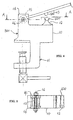
- FIGS 4 and 5 show a third embodiment of a moulding tool in accordance with the present invention, under the general reference 300.
- the moulding tool 300 is basically a manual press and has a body 10 provided underneath with a clamp 11 for fixing it to a workbench (not shown).
- a hand actuated bar 13 is hinged to the body 10 between two trunnions 14.
- the bar 13 comprises a hub 15 mounted on a stationary pin 16 at the opposite end from the hand end.
- the bar 13 carries a convex half or punch 500 mounted transversely in a position such as to arrive in a moulding relationship with the concave half 400.
- the moulding operation is basically the same as that performed with the first embodiment 3 of the tool as far as the disposition of the lock of hair relative to the tool is concerned. As is obvious, productivity and convenience of work are improved because the tool does not have to be held in the operator's hand.
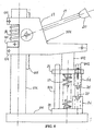
- FIG. 6 A fourth embodiment of the moulding tool in accordance with the present invention is shown in Figure 6 under the general reference 301.
- the moulding tool 301 is basically a manual press in which the advancing movement is provided by the operator by an arrangement similar to that usually used in a so-called sensitive drill.
- the tool 301 has a base 100 solid enough to keep it stable on a work surface and hold it in a fixed position throughout operation without the need for fixing means.
- Fixed vertically to the base 100 is a column 101, which may be a cylindrical column, supporting a rack 102.
- Mounted movably on the column 101 by two rear arms 170 and 171 that encircle the column 101 is a bracket 17.
- the stroke of the bracket 17 up and down the column 101 is limited by a shoulder 103 fastened to the column 101 in the gap between the rear arms 170 and 171 of the bracket 17.
- Sitting between the mutually confronting surfaces of the shoulder 103 and the rear arm 170 is a helical spring 18.
- An actuating lever 19, with a hand grip 20 at the end (shown partially), is hinged in a known way to the bracket 17 with a pinion (not shown) engaging with the rack 102.
- the plate 22 has integral vertical guide pins 201, 202 for the ram plate 21, and the latter has corresponding through holes for the vertical pins 201, 202.
- Fitted between the plate 22 and the ram plate 21 is a helical spring 23.
- Fixed vertically to and downwards from the ram plate 21 is a prismatic component 24, its major axis being perpendicular to the plane of the drawing paper, with a convex U-profile punch 25 in its free end.
- the plate 22 supports a prismatic component 26, its major axis similarly perpendicular to the drawing paper, with a concave die 27 of identical U profile in its free end.
- One end of the hair extension, to which the thermoplastic resin has been applied, is laid in the cavity of the concave die 27.
- the operator acting on the lever 19 against both opposing springs 18 and 23, brings the punch 25 down onto the die 27 and compresses the resin and the ends of the hairs between their respective convex and concave surfaces.
- the punch 25 is withdrawn from the die 27 by the action of the opposing springs and the hair extension is removed.
- the tool 301 in the fourth embodiment can be conveniently moved to where it is needed without time being wasted on installation.
- the punch is introduced into the die with a rectilinear motion rather than a rotary one. This makes the moulding symmetrically uniform and produces a shell of more even thickness.
- Removal from the mould is automatic because of the opposing springs, as soon as: the operator releases the actuating lever 19. This reduces processing time.
- the greater length in the perpendicular direction of the die and punch enables the shell to be reduced subsequently to the desired dimension.
Description
- The present invention relates to a method of preparing hair extensions for creating hairstyles, a tool for the said method and an extension prepared by this method.
- A number of currently fashionable hairstyles require the attachment to the person's natural hair of hair extensions in, for example, the form of ponytails, plaits and the like. These extensions are attached to the natural hair and removed from it as the wearer requires.
- In current practice, through US-A-4 934 387, these known hair extensions are prepared by bonding natural hair or artificial hair (the latter will also be called hair in this text), or the like, together at one end with a small quantity of adhesive substance, usually a thermoplastic resin. This operation is performed by holding the lock of hair in the fingers of one hand; the other hand then applies a drop of heated, and therefore fluid, resin onto the ends of the hair. The hairs are then worked and twisted between the fingers to form, with the consequent immediate hardening of the resin once it has cooled, a cylinder comprising resin and hair, similar to a slubbing or roving.
- For use, the hair extension is heated with a suitable tool on the roving as prepared above and joined to the natural hair, or indeed to a wig, where desired.
- US-A-4 982 748 shows such a kind of tool, comprising a pair of tip members which are adapted for mounting on arm members of a conventional curling iron. The tip members include pointed portions and opposing flat surfaces which facilitate the application of heat to a wrapped four-piece braid of both filaments and normal hair to be extended.
- The known method described above has many drawbacks, some to do with the use of the fingers alone in the preparation of the hair extension and others due to the resulting hair extension and its subsequent attachment to the wearer's hair.
- More specifically, in the operation of bonding the ends of the hairs of the extension, the fingers tend to stick to the hair extension and the result is an irregular cylinder.
- Moreover, contact between the operator's fingers and the resin can cause scalding and irritation of the skin and the known method is therefore not acceptable from the point of view of safety at work.
- Lastly, in its practical application, a cylindrical roving of twisted hairs combines poorly with the person's own hair, creating an obvious visible contrast and an unnatural join.
- The object of the present invention is therefore to overcome the abovementioned disadvantages.
- More specifically, the present invention relates to a method of preparing hair extensions for creating hairstyles, in which a quantity of thermoplastic resin is applied in the fluid state to one end of a lock of natural or artificial hairs in order to bond them together to form a hair extension, forming a concave shell, similar in form to a fingernail, which is suitable for the subsequent accommodation in the abovementioned concavity of a lock of the wearer's own hair to which the hair extension is to be attached.
- In addition, the method according to the invention is such as to comply with work safety standards.
- According to the present invention, a method of preparing hair extensions comprises the following steps:
- placing ends of the hairs of a hair extension, with applied drop of resin at the fluid state on a concave surface which is non-stick with respect to the thermoplastic resin;
- compressing the thermoplastic resin and the ends of the hairs between the concave surface and a corresponding convex surface that is likewise non-stick with respect to the thermoplastic resin;
- removing the ends of the hairs in contact with the thermoplastic resin which has been moulded into a concave shell similar in form to a fingernail, and which becomes rigid once the resin has cooled; and finishing the concave shell to the desired dimensions.
- The invention additionally provides, for the preparation of hair extensions for creating hairstyles, a tool, such as a compressive moulding tool comprising a concave half or die and a convex half or punch, preferably made of a non-stick material with respect to the thermoplastic resin, in which the halves of the moulding tool are movable towards each other to compress the end of the lock of hair in contact with the thermoplastic resin, and away from each other after compression and hardening, for moulding the thermoplastic resin into a concave shell similar in form to a fingernail.
- For small-scale production, the moulding tool, preferably of manual type, is made from a pair of pliers or a bench press fitted with concave and convex moulding halves. For production on a larger scale, the tool may be equipped with motors and servocontrols allowing it to operate semi-automatically or automatically.
- The present invention also provides a hair extension for creating hairstyles produced by the method of the invention, in which the hairs of a lock are bonded at one end in a concave shell of thermoplastic resin shaped like a fingernail.
- The present invention will now be described with reference to a preferred embodiment, and on the basis of the figures of the attached drawings, wherein:
- Figure 1 is an illustrative perspective view of the hair extension according to the present invention;
- Figure 2 is a side view of a first embodiment of the tool according to the present invention;
- Figure 3 is a partial side view of a second embodiment of the tool according to the present invention;
- Figure 4 is a side view of a third embodiment of the tool according to the present invention;
- Figure 5 is a section on A-A as marked in Figure 4; and
- Figure 6 shows schematically a side view of a fourth embodiment of the tool according to the present invention.
-
- The method of preparing hair extensions for creating hairstyles in accordance with the present invention provides for the application of a limited quantity of thermoplastic resin to one end of a lock of natural or artificial hairs in order to bond them together to form a hair extension. More precisely, a drop of thermoplastic resin, usually of the so-called "hot-melt" type (such as that marketed under the trade name Tubitrans Melt), made fluid by heating, is dropped onto the ends of the hairs of the hair extension that is to be formed, which latter is then placed on a concave surface to which the thermoplastic resin will not stick.
- According to the present invention, the abovementioned concave surface is that of a die designed to engage, in a moulding operation, with a punch, the material of the latter also preferably being non-stick with respect to the thermoplastic resin, having a corresponding cylindrical surface. The die and punch are installed in a compressive moulding tool, which will be described later in a variety of embodiments shown in Figures 2 to 6.
In order to make the moulding operation possible, the die and the punch are movable towards each other to compress the end of the lock of hair to which the thermoplastic resin has been applied and then away from each other after compression and hardening of the resin in a concave shape. - This concave die surface is preferably a portion of the lateral surface of a cylinder whose diameter is greater the greater the quantity of hair which the resin is to bond.
- The portion of the lateral surface of the die is bounded by two cylindrical generatrices passing through the same semicircular base.
- This serves to permit engagement between the die and the punch without the creation of undercuts that would be useless and damaging in the operation of removing the hair extension.
- The hair extension is removed from the tool after the rapid cooling of the resin and its consequent hardening, and finished by limiting the length of the portion covered by the resin, as shown by way of example in Figure 1.
- Referring to this Figure 1, the hair extension comprises a lock 1 of natural or artificial hairs, which can be straight or curly, loose or plaited, bonded at one end in a concave shell 2 consisting of hardened thermoplastic resin, roughly similar in form to a fingernail.
- This shape is highly suitable for the subsequent attachment of the resulting hair extension to a person's hair. For this process the concave shell will be heated with a suitable tool and applied around a lock of the person's own hair to form a special hairstyle, e.g. a ponytail, plait or the like, to which other embellishments may also be added.
- When desired, the hair extension is removed in the conventional way by breaking up the resin-bound end with a suitable pair of pliers and applying a known liquid solvent, such as for example 90° ethyl alcohol or cosmetic acetone, to this broken up portion after which the hair extension is removed.
- Figure 2 shows a first embodiment of a moulding tool for preparing a hair extension in accordance with the present invention, to which the
general reference 3 is given. Themoulding tool 3 is essentially a pair of pliers whosetips 4, 5 carry the concave moulding half or die 6 and the convex moulding half or punch 7, respectively. - As is clear, in this first embodiment of the tool the respective axes of symmetry of the die and punch 6, 7 (these axes are not indicated in the figure) are perpendicular to the plane containing the axes of symmetry of the
tips 4, 5 of the pliers (these axes are also not indicated in the figure). - In order to prepare the hair extension, a drop of resin, heated until fluid, is applied to the end of the lock of hair, the hair extension is then laid in the die 6, and the
tips 4, 5 are brought together, closing the pliers, and, after the resin has hardened, the tips are separated again. The hair extension can be taken out for finishing. - Figure 3 shows part of a second embodiment of a moulding tool in accordance with the present invention, having the
general reference 30. Themoulding tool 30 is once again basically a pair of pliers, thetips die 60 and thepunch 70, respectively. In this second embodiment of the tool, the respective axes of symmetry (not indicated in the figure) of the die andpunch tips punch 70 is essentially cylindrical while the die 60 comprises symmetrically extended walls 61 inclined slightly outwards relative to theinner portion 62 of the die. This facilitates the placing of the end of the lock of hair in the die 60. - The moulding operation is basically the same as for the
first embodiment 3 of the tool, the only difference being the disposition of the lock of hair relative to the pliers. - Figures 4 and 5 show a third embodiment of a moulding tool in accordance with the present invention, under the
general reference 300. Themoulding tool 300 is basically a manual press and has abody 10 provided underneath with aclamp 11 for fixing it to a workbench (not shown). - On the top of the
body 10 is ananvil 12 for aconcave moulding half 400. A hand actuated bar 13 is hinged to thebody 10 between twotrunnions 14. For this purpose the bar 13 comprises ahub 15 mounted on astationary pin 16 at the opposite end from the hand end. - The bar 13 carries a convex half or punch 500 mounted transversely in a position such as to arrive in a moulding relationship with the
concave half 400. - The moulding operation is basically the same as that performed with the
first embodiment 3 of the tool as far as the disposition of the lock of hair relative to the tool is concerned. As is obvious, productivity and convenience of work are improved because the tool does not have to be held in the operator's hand. - A fourth embodiment of the moulding tool in accordance with the present invention is shown in Figure 6 under the
general reference 301. Like thetool 300 described earlier, themoulding tool 301 is basically a manual press in which the advancing movement is provided by the operator by an arrangement similar to that usually used in a so-called sensitive drill. Thetool 301 has a base 100 solid enough to keep it stable on a work surface and hold it in a fixed position throughout operation without the need for fixing means. Fixed vertically to thebase 100 is acolumn 101, which may be a cylindrical column, supporting arack 102. Mounted movably on thecolumn 101 by tworear arms column 101 is abracket 17. The stroke of thebracket 17 up and down thecolumn 101 is limited by ashoulder 103 fastened to thecolumn 101 in the gap between therear arms bracket 17. Sitting between the mutually confronting surfaces of theshoulder 103 and therear arm 170 is a helical spring 18. Anactuating lever 19, with ahand grip 20 at the end (shown partially), is hinged in a known way to thebracket 17 with a pinion (not shown) engaging with therack 102. Mounted on the front of thebracket 17, by means of avertical post 172, is aram plate 21 held above an opposing plate 22 fixed to thebase 100. The plate 22 has integral vertical guide pins 201, 202 for theram plate 21, and the latter has corresponding through holes for thevertical pins ram plate 21 is ahelical spring 23. Fixed vertically to and downwards from theram plate 21 is aprismatic component 24, its major axis being perpendicular to the plane of the drawing paper, with a convexU-profile punch 25 in its free end. Corresponding to this, the plate 22 supports aprismatic component 26, its major axis similarly perpendicular to the drawing paper, with aconcave die 27 of identical U profile in its free end. - The moulding operation is very much the same as that performed with the tool of the third embodiment illustrated in Figures 4 and 5.
- One end of the hair extension, to which the thermoplastic resin has been applied, is laid in the cavity of the
concave die 27. The operator, acting on thelever 19 against both opposingsprings 18 and 23, brings thepunch 25 down onto thedie 27 and compresses the resin and the ends of the hairs between their respective convex and concave surfaces. - The
punch 25 is withdrawn from the die 27 by the action of the opposing springs and the hair extension is removed. - The advantages are obvious, not only when compared with the pliers versions shown in Figures 2 and 3, but also when compared with the tool fitted with the clamp as shown in Figures 4 and 5.
- The
tool 301 in the fourth embodiment can be conveniently moved to where it is needed without time being wasted on installation. - In this tool the punch is introduced into the die with a rectilinear motion rather than a rotary one. This makes the moulding symmetrically uniform and produces a shell of more even thickness.
- Removal from the mould is automatic because of the opposing springs, as soon as: the operator releases the actuating
lever 19. This reduces processing time. - Although the compressive load employed in moulding the portion of hair with resin is not excessive, it is still reduced by the engagement of the pinion and rack pair connected to the actuating lever, as compared with a lever that is simply hinged as in the third embodiment.
- The lengthened design of the U profile of the
punch 25 and of the die 27, combined perpendicularly with theprismatic components - The greater depth of the die, together with its length in the perpendicular direction, improves and facilitates the positioning of the end of the hair extension. It also means that a larger quantity of hair can be accommodated and therefore thicker hair extensions can be obtained.
- The greater length in the perpendicular direction of the die and punch enables the shell to be reduced subsequently to the desired dimension.
- As stated earlier, it is easy, without departing from the scope of the invention, to devise partly or fully automatic motorized equipment capable of executing the same moulding operation for the preparation of hair extensions by the method of the invention.
- The present invention has been described with reference to certain currently preferred embodiments thereof, but it will be understood that practical alterations and modifications may be made by those skilled in the art without departing from the scope of protection of this intellectual property document.
Claims (10)
- Method of preparing hair extensions for creating hairstyles, in which a quantity of thermoplastic resin is applied as a drop in a fluid state obtained by heating to one end of a lock (1) of natural or artificial hairs in order to bond them together to form a hair extension, characterized in that it further comprises the following steps:placing the end of lock (1) with the applied drop of resin on a concave surface which is non-stick with respect to the thermoplastic resin;compressing the thermoplastic resin and the end of lock (1) between the concave surface and a corresponding convex surface that is likewise non-stick with respect to the thermoplastic resin;removing the end of lock (1) in contact with the thermoplastic resin which has been moulded into a concave shell (2) similar in form to a fingernail, and which becomes rigid once the resin has cooled; andfinishing the shell (2) to the desired dimensions.
- Method according to Claim 1, characterized in that the thermoplastic resin is of the so-called hot-melt type.
- Tool for preparing hair extensions for creating hairstyles according to the method of Claim 1, such as a compressive moulding tool (6, 7; 60, 70; 400, 500; 27, 25) comprising a concave half or die (6; 60; 400; 27) and a convex half or punch (7; 70; 500; 25) preferably made of a non-stick material with respect to the thermoplastic resin; characterized in that the halves (6, 7; 60, 70; 400, 500; 27, 25) of the moulding tool are movable towards each other to compress the end of the lock (1) of hair in contact with the thermoplastic resin, and away from each other after compression and hardening of the resin, for moulding the thermoplastic resin into a concave shell (2) similar in form to a fingernail.
- Tool according to Claim 3, characterized in that the said moulding tool (3) is a pair of pliers, one (4) of whose tips (4, 5) carries the concave moulding half (6) and the other (5) the convex moulding half (7) these halves (6, 7) having respective axes of symmetry coinciding with the axes of symmetry of the tips (4, 5) of the pliers.
- Tool according to Claim 3, characterized in that the said moulding tool (30) is a pair of pliers, one (40) of whose tips (40, 50) carries the concave moulding half (60) and the other (50) the convex moulding half (70) these halves (60, 70) having respective axes of symmetry perpendicular to the plane containing the axes of symmetry of the tips (40, 50) of the pliers.
- Tool according to Claim 3, characterized in that the said moulding tool (300) is a manual press having a body (10) provided underneath with a clamp (11) for fixing it to a workbench, while on top is an anvil (12) for the concave moulding half (400) and a hand actuated bar (13) hinged to the body (10) and carrying the convex moulding half (500) in a position such as to arrive in a moulding relationship with the concave half (400).
- Tool according to Claim 3, characterized in that the said moulding tool (301) is a manual press comprising:a supporting base (100),a column (101) fixed vertically to the base (100) and supporting a rack (102),a bracket (17) with two rear arms (170, 171) by which it is mounted on the column (101), and able to move in a spring-loaded stroke limited by a shoulder (103) fastened to the column (101) in the gap between the rear arms (170, 171) of the bracket (17),a hand actuated lever (19) hinged to the bracket (17) and having a pinion engaging with the column rack (102), anda ram plate (21) having a U-shaped convex punch (25), mounted at the front, on the bracket (17), above a plate (22) that comprises a U-shaped concave die (27) and is fixed to the support base (100).
- Tool according to Claim 7, characterized in that the plate (21) has integral vertical guide pins (201, 202) for a spring-loaded stroke of the ram plate (21), which contains through holes corresponding to the pins (201, 202).
- Tool according to Claim 7, characterized in that the die (27) and the punch (25) are attached to the plate (22) and ram plate (21), respectively, on respective prismatic components (26, 24).
- Hair extension for creating hairstyles, produced by the method of Claim 1, characterized in that it has a lock (1) of hair bonded at one end in a concave shell (2) of thermoplastic resin shaped like a fingernail.
Applications Claiming Priority (2)
| Application Number | Priority Date | Filing Date | Title |
|---|---|---|---|
| ITRM970202 | 1997-04-11 | ||
| IT97RM000202 IT1298485B1 (en) | 1997-04-11 | 1997-04-11 | TOOL FOR THE PREPARATION OF POSTICCE FOR HAIRSTYLES |
Publications (2)
| Publication Number | Publication Date |
|---|---|
| EP0876773A1 EP0876773A1 (en) | 1998-11-11 |
| EP0876773B1 true EP0876773B1 (en) | 2001-09-26 |
Family
ID=11404955
Family Applications (1)
| Application Number | Title | Priority Date | Filing Date |
|---|---|---|---|
| EP19980830205 Expired - Lifetime EP0876773B1 (en) | 1997-04-11 | 1998-04-03 | Method, apparatus and hair extension product thereof |
Country Status (4)
| Country | Link |
|---|---|
| EP (1) | EP0876773B1 (en) |
| DE (1) | DE69801786T2 (en) |
| ES (1) | ES2162408T3 (en) |
| IT (1) | IT1298485B1 (en) |
Families Citing this family (8)
| Publication number | Priority date | Publication date | Assignee | Title |
|---|---|---|---|---|
| AT412141B (en) * | 2002-12-23 | 2004-10-25 | Bege Privatstiftung | U-SHAPED THERMOPLASTIC HAIR FASTENER |
| US7661434B2 (en) | 2003-01-03 | 2010-02-16 | Frazier Carol W | Hair-on-hair extension system |
| US7320327B2 (en) | 2003-02-13 | 2008-01-22 | Carol Frazier | Hair extension attachment |
| US6832614B2 (en) | 2003-01-03 | 2004-12-21 | Carol W. Frazier | Hair extension attachment |
| AU2003259636B2 (en) * | 2003-11-04 | 2009-10-01 | Evadney Edeta Wootton | Hair Extension Tool |
| NL1030766C2 (en) | 2005-12-23 | 2007-06-26 | Euro Hair Fashion Holding B V | Hair extension removal device, includes hand operated clamp and removable solvent reservoir for breaking adhesive bond between hair and extension |
| CN103734961B (en) * | 2014-01-13 | 2015-07-15 | 李科修 | Camber memory false eyelashes and preparation method and using method thereof |
| US10561185B2 (en) | 2016-09-28 | 2020-02-18 | Jessica Harris | Tool for simultaneously attaching multiple hair extensions |
Family Cites Families (3)
| Publication number | Priority date | Publication date | Assignee | Title |
|---|---|---|---|---|
| US4982748A (en) * | 1988-04-04 | 1991-01-08 | Trimarchi Adriana L | Method for lengthening normal hair |
| US4934387A (en) * | 1989-05-05 | 1990-06-19 | Salvatore Megna | Hair extension process |
| EP0760215B1 (en) * | 1995-08-28 | 1999-01-13 | Blond & Braun Haarwarenerzeugungs- u. Handels- Ges.m.b.H. | Method for attaching hair wigs (toupet locks) to the hair of a subject using metallic tubes |
-
1997
- 1997-04-11 IT IT97RM000202 patent/IT1298485B1/en active IP Right Grant
-
1998
- 1998-04-03 EP EP19980830205 patent/EP0876773B1/en not_active Expired - Lifetime
- 1998-04-03 ES ES98830205T patent/ES2162408T3/en not_active Expired - Lifetime
- 1998-04-03 DE DE1998601786 patent/DE69801786T2/en not_active Expired - Fee Related
Also Published As
| Publication number | Publication date |
|---|---|
| ITRM970202A1 (en) | 1998-10-11 |
| DE69801786T2 (en) | 2002-02-21 |
| EP0876773A1 (en) | 1998-11-11 |
| IT1298485B1 (en) | 2000-01-10 |
| ES2162408T3 (en) | 2001-12-16 |
| DE69801786D1 (en) | 2001-10-31 |
Similar Documents
| Publication | Publication Date | Title |
|---|---|---|
| EP0876773B1 (en) | Method, apparatus and hair extension product thereof | |
| US4982748A (en) | Method for lengthening normal hair | |
| JP5925986B2 (en) | Equipment for hair curling and / or hair styling | |
| US6191387B1 (en) | Hair styling tongs with biased handles | |
| KR102092488B1 (en) | Cosmetic refill for hair treatment device with heating element and hair treatment device comprising the refill | |
| KR930006491B1 (en) | Applicator for make-up use, method for producing the same, and apparatus for effecting the method | |
| KR20050102699A (en) | Iron for shaping hair | |
| JP2011516749A (en) | Hair extension assembly for use in hair extension attachment methods, application clamps, pinch applicators and methods | |
| JP6832612B2 (en) | Hair styling device | |
| KR101323076B1 (en) | Attaching device for extension eyelashes | |
| CN101351134B (en) | Apparatus for processing hair | |
| US7036517B2 (en) | Applicator for replacement hair strands | |
| KR20030038413A (en) | Eyelash curler | |
| BE1017068A3 (en) | Hair extension, comprises hair filaments attachable to hair via heat shrinkable plastic strip | |
| US4149335A (en) | Process for forming fishing lure component and article formed thereby | |
| JP4135286B2 (en) | Eyelash forming tool | |
| JP3850633B2 (en) | Eyelash curler | |
| US20020066460A1 (en) | Synthetic hair crimper | |
| JP2000060643A (en) | Manufacture of toothbrush | |
| JPS5949918A (en) | Monolithic molding method of skin material and resin | |
| CN218457171U (en) | Novel plucking clamp | |
| CN210120961U (en) | Hair straightening device | |
| CN210446019U (en) | Straight dual-purpose curling hair-dressing molding device | |
| JP4125695B2 (en) | Substitute tufted applicator | |
| JPH078395B2 (en) | Swaging device |
Legal Events
| Date | Code | Title | Description |
|---|---|---|---|
| PUAI | Public reference made under article 153(3) epc to a published international application that has entered the european phase |
Free format text: ORIGINAL CODE: 0009012 |
|
| AK | Designated contracting states |
Kind code of ref document: A1 Designated state(s): DE ES FR GB IT |
|
| AX | Request for extension of the european patent |
Free format text: AL;LT;LV;MK;RO;SI |
|
| 17P | Request for examination filed |
Effective date: 19990419 |
|
| AKX | Designation fees paid |
Free format text: DE ES FR GB IT |
|
| 17Q | First examination report despatched |
Effective date: 20000905 |
|
| GRAG | Despatch of communication of intention to grant |
Free format text: ORIGINAL CODE: EPIDOS AGRA |
|
| GRAG | Despatch of communication of intention to grant |
Free format text: ORIGINAL CODE: EPIDOS AGRA |
|
| GRAH | Despatch of communication of intention to grant a patent |
Free format text: ORIGINAL CODE: EPIDOS IGRA |
|
| GRAH | Despatch of communication of intention to grant a patent |
Free format text: ORIGINAL CODE: EPIDOS IGRA |
|
| GRAA | (expected) grant |
Free format text: ORIGINAL CODE: 0009210 |
|
| AK | Designated contracting states |
Kind code of ref document: B1 Designated state(s): DE ES FR GB IT |
|
| REF | Corresponds to: |
Ref document number: 69801786 Country of ref document: DE Date of ref document: 20011031 |
|
| ET | Fr: translation filed | ||
| REG | Reference to a national code |
Ref country code: ES Ref legal event code: FG2A Ref document number: 2162408 Country of ref document: ES Kind code of ref document: T3 |
|
| REG | Reference to a national code |
Ref country code: GB Ref legal event code: IF02 |
|
| PLBE | No opposition filed within time limit |
Free format text: ORIGINAL CODE: 0009261 |
|
| STAA | Information on the status of an ep patent application or granted ep patent |
Free format text: STATUS: NO OPPOSITION FILED WITHIN TIME LIMIT |
|
| 26N | No opposition filed | ||
| PGFP | Annual fee paid to national office [announced via postgrant information from national office to epo] |
Ref country code: IT Payment date: 20060430 Year of fee payment: 9 |
|
| PGFP | Annual fee paid to national office [announced via postgrant information from national office to epo] |
Ref country code: DE Payment date: 20070717 Year of fee payment: 10 Ref country code: ES Payment date: 20070717 Year of fee payment: 10 |
|
| PGFP | Annual fee paid to national office [announced via postgrant information from national office to epo] |
Ref country code: GB Payment date: 20070718 Year of fee payment: 10 |
|
| PGFP | Annual fee paid to national office [announced via postgrant information from national office to epo] |
Ref country code: FR Payment date: 20070719 Year of fee payment: 10 |
|
| GBPC | Gb: european patent ceased through non-payment of renewal fee |
Effective date: 20080403 |
|
| PG25 | Lapsed in a contracting state [announced via postgrant information from national office to epo] |
Ref country code: DE Free format text: LAPSE BECAUSE OF NON-PAYMENT OF DUE FEES Effective date: 20081101 |
|
| REG | Reference to a national code |
Ref country code: FR Ref legal event code: ST Effective date: 20081231 |
|
| PG25 | Lapsed in a contracting state [announced via postgrant information from national office to epo] |
Ref country code: FR Free format text: LAPSE BECAUSE OF NON-PAYMENT OF DUE FEES Effective date: 20080430 |
|
| REG | Reference to a national code |
Ref country code: ES Ref legal event code: FD2A Effective date: 20080404 |
|
| PG25 | Lapsed in a contracting state [announced via postgrant information from national office to epo] |
Ref country code: GB Free format text: LAPSE BECAUSE OF NON-PAYMENT OF DUE FEES Effective date: 20080403 |
|
| PG25 | Lapsed in a contracting state [announced via postgrant information from national office to epo] |
Ref country code: ES Free format text: LAPSE BECAUSE OF NON-PAYMENT OF DUE FEES Effective date: 20080404 |
|
| PG25 | Lapsed in a contracting state [announced via postgrant information from national office to epo] |
Ref country code: IT Free format text: LAPSE BECAUSE OF NON-PAYMENT OF DUE FEES Effective date: 20070403 |