EP0965365A2 - Frame for exercise machines - Google Patents
Frame for exercise machines Download PDFInfo
- Publication number
- EP0965365A2 EP0965365A2 EP99830362A EP99830362A EP0965365A2 EP 0965365 A2 EP0965365 A2 EP 0965365A2 EP 99830362 A EP99830362 A EP 99830362A EP 99830362 A EP99830362 A EP 99830362A EP 0965365 A2 EP0965365 A2 EP 0965365A2
- Authority
- EP
- European Patent Office
- Prior art keywords
- cross member
- uprights
- section
- pair
- frame according
- Prior art date
- Legal status (The legal status is an assumption and is not a legal conclusion. Google has not performed a legal analysis and makes no representation as to the accuracy of the status listed.)
- Withdrawn
Links
Images
Classifications
-
- A—HUMAN NECESSITIES
- A63—SPORTS; GAMES; AMUSEMENTS
- A63B—APPARATUS FOR PHYSICAL TRAINING, GYMNASTICS, SWIMMING, CLIMBING, OR FENCING; BALL GAMES; TRAINING EQUIPMENT
- A63B21/00—Exercising apparatus for developing or strengthening the muscles or joints of the body by working against a counterforce, with or without measuring devices
- A63B21/06—User-manipulated weights
- A63B21/062—User-manipulated weights including guide for vertical or non-vertical weights or array of weights to move against gravity forces
- A63B21/0626—User-manipulated weights including guide for vertical or non-vertical weights or array of weights to move against gravity forces with substantially vertical guiding means
- A63B21/0628—User-manipulated weights including guide for vertical or non-vertical weights or array of weights to move against gravity forces with substantially vertical guiding means for vertical array of weights
-
- A—HUMAN NECESSITIES
- A63—SPORTS; GAMES; AMUSEMENTS
- A63B—APPARATUS FOR PHYSICAL TRAINING, GYMNASTICS, SWIMMING, CLIMBING, OR FENCING; BALL GAMES; TRAINING EQUIPMENT
- A63B2225/00—Miscellaneous features of sport apparatus, devices or equipment
- A63B2225/30—Maintenance
Definitions
- the present invention relates to a frame for exercise machines.
- exercise machine of the isotonic type i.e. of the type with counterweights, or provided with electronically controlled resistant assemblies, comprise a frame presenting two uprights, an upper cross member and a lower cross member which connect the two uprights together in correspondence with the respective upper and lower end portions.
- the frame further comprises structural elements such as beams, arms or other accessory structures, able to define the supports for the elements whereon the user can bear down and properly position him/herself while exercising on the machine.
- structural elements such as beams, arms or other accessory structures, able to define the supports for the elements whereon the user can bear down and properly position him/herself while exercising on the machine.
- the frame 1 in question is part of an isotonic exercise machine, which machine is not shown herein with reference to its other accessory parts, since they are known and not comprised in the invention.
- the frame 1 comprises a pair of uprights 2 and 3 substantially identical and mutually connected, in correspondence with respective upper ends, by an upper cross member 4, and, in correspondence with a respective lower end, by a lower cross member 6.
- the uprights 2 and 3 are slightly arched outwards, thereby conferring greater stability to the frame 1: in practice the uprights 2 and 3, together with the cross member 4, have outwardly concave development.
- the frame 1 is symmetrical with respect to an axis (not shown) that is substantially vertical and equidistant from the uprights 2 and 3, and is substantially shaped as a "portal".
- the weight pack 10 is able to slide, in the two directions, on the vertical bars 11 and 12 and can be actuated by the user through a pulley and flexible cable transmission (not shown herein) supported by the frame 1.
- the weight pack 10 is positioned in the lower part of the frame, but it can be positioned at different heights with respect to a treadable plane P, without any loss of originality in the present description.
- the uprights 2 and 3 and the aforesaid upper cross member 4 are realized with a respective first tubular bar 5 with rounded cross section, similar to a flattened circular section. Without detracting from the originality of the present description, the section of the first tubular bar 5 can be defined as oval.
- Fig. 1 also shows, to complete the frame 1, a lower cross member 6, bilaterally connected to the pair of uprights 2 and 3 and preferentially comprising a second tubular bar 7 with oval section geometrically similar to the first tubular bar 5.
- this second tubular bar 7 presents an essentially identical cross section to that of the first tubular bar 5.
- the pair of uprights 2 and 3 and the upper cross member 4 can be obtained in a single type of tubular cross member with oval/elliptical cross section, i.e. these elements are obtained from the same base section bar.
- the architecture of the uprights 2 and 3 presents an arched and mutually opposite development, when the frame 1 is assembled, and the upper cross member 4 is also arched: in this way a portal is created that is shaped as an upside down "U” with rounded edges, closed at the bottom by the lower cross member 6.
- each isotonic machine is designed with the purpose of training a determined muscle district; hence, the vertical extension of the uprights 2 and 3 will be proportionate to the amount of mass necessary to train the muscle set.
- the uprights 2 and 3 of a leg press will have greater extension than that of the uprights of a pectoral muscle press.
- the width of the portal, as well as the curvature / arch radius of the uprights 2 and 3 and of the cross member 4 may be proportioned accordingly.
- Fig. 3 shows that between the extremities 4a and 4b of the aforesaid upper cross member 4 and the respective upper extremities 2a and 3a of the pair of uprights 2 and 3, means 8 are provided for rapid coupling, for instance by snapping, in correspondence with the junctions 9 of the upper cross member 4 with the pair of uprights 2 and 3.
- these rapid coupling means 8 may be constituted by a bayonet coupling device comprising a plurality of retractable teeth 20 positioned on a related end section 21 realized on the corresponding extremity 4a and 4b of the upper cross member 4 and presenting smaller size with respect to the size of the corresponding extremity 2a and 3a of the uprights 2 and 3.
- the coupling of the cross member 4 (according to the direction F) on the uprights 2 and 3 is assured thanks to corresponding internal projections 22 present on the uprights 2 and 3, which determine an initial inward motion of the teeth 20 during the insertion of the cross member 4 and a subsequent stop against the teeth themselves, in the advanced position, upon completion of the coupling operation.
- the frame 1 is equivalent to a frame obtained by bending with variable radius from a single tubular bar with oval section. In this way the junctions 9 would be realized automatically during the bending operation itself.
- the "portal" frame 1, that is the uprights 2, 3 and the upper cross member 4 could be realized as a whole starting from a single tubular bar (having an oval cross section) which is bent in correspondence of the curved portions indicated with the reference 9c.
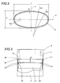
- the oval shape (which could also be defined by an ellipse) is preferentially definable as per Fig. 2, in which the greater and respectively smaller axes X, Y define the values of length L and width H.
- Fig. 2 also shows three values of radius of curvature that realize, in their combination, the resulting oval combination: these radii are R1, the smallest, R2 the intermediate one and R3 the largest.
- the thickness S of the tubular bar itself can lie within a range of values from 1 to 4 mm, and it preferably shall be 2.5 mm.
- the choice of an oval section for the constructive elements of the frame 1 allows to reduce the specific weight of the structure (computed on the basis of the length of the axis of the tubular elements) maintaining at least unchanged the mechanical resistance of the structure to the loads oriented according to the direction of elongation of the oval section itself.
- the frame 1 presents greater rigidity than a quadrangular section of substantially identical weight (and thus presenting greater thickness). Maintaining constant the specific weight computed with respect to the length of the tubular bars and increasing the internal volumes to the uprights 2 and 3, it is also possible to increase mechanical strength, at the same time reducing thickness.
- the enhanced rigidity and mechanical strength, and the simultaneous weight limitation, also allow to obtain isotonic machines with frames 1 that are less bulky and free of stiffening arms. These machines are thus easy to move and safer, presenting fewer projections and hindrances to the users' access.
- the gradual variation of the curvature radii of the sections of the cross members and of the axes of the uprights 2 and 3 limits dust accumulation, facilitating cleaning operations.
- the frame 1 from the constructive standpoint as a plurality of individual lengths mutually connected in a rigid manner (and also because of the reduced value of thickness of the uprights 2 and 3 and cross members 4 and 6), in the frame 1 the geometric axes of the adjacent lengths of tube will substantially coincide with the axis of transmission of the stress acting under load. Since the stresses that the adjacent lengths transmit to each other are substantially normal stresses, the frames will be particularly well balanced under load thanks to the substantial absence of transverse loads.
- the large inner section of the tubular bars obtained with the oval/elliptical conformation, allows conveniently to house accessory elements, such as electrical wires, driving cables, pulleys, etc., without having to occupy space outside the frame.
- accessory elements such as electrical wires, driving cables, pulleys, etc.
- the internal positioning of these accessories allows to simplify the structure of the machine and to make it easily accessible to the user without his/her having to walk over metal or electrical cables.
- the possible reversible coupling of the upper cross member allows to obtain an easier access to the interior part of the tubular bars comprising the frame for any ordinary or extraordinary maintenance operations.
Abstract
Description
- The present invention relates to a frame for exercise machines.
- Normally, exercise machine of the isotonic type, i.e. of the type with counterweights, or provided with electronically controlled resistant assemblies, comprise a frame presenting two uprights, an upper cross member and a lower cross member which connect the two uprights together in correspondence with the respective upper and lower end portions.
- These constructive elements define a structure which, in counterweight machines, supports a pair of vertical bars positioned between the upper and lower cross members. Such bars serve the purpose of vertically guiding a so-called "weight pack", defined by a plurality of bricks of determined weight, able to be actuated in alternating motion by a user through the interposition of a transmission with a flexible cable wound on pulleys, which are supported by the frame itself.
- The frame further comprises structural elements such as beams, arms or other accessory structures, able to define the supports for the elements whereon the user can bear down and properly position him/herself while exercising on the machine.
- In the prior art, the realization is known of such frames for isotonic machines by mutually connecting tubular beams with quadrangular cross section, cut to measure and welded together in correspondence with respective end portions to obtain junctions which, normally, have sharp edges. Essentially, exercise machine frames derive from classic "metalwork" operations performed on tubular members with sharp-edged cross sections, i.e. by means of cutting and welding operations and, occasionally, due to assembly requirements, by means of threaded connections, through the use of traditional metal profiles which are adapted, on a case by case basis, to the dimensional needs of the resulting machine.
- The continuous advance of training methodologies has entailed the growing use of electronics and information technology on such isotonic machines. Hence the machines present, in addition to traditional kinematic mechanisms for the equipment, also electric wires, exercise recording units, sensors for controlling the position of the weight pack, etc., which are supported by the frame of the machine itself.
- Traditional frames, having been devised exclusively to sustain external mechanical accessories, are not suited to support and/or house the new equipment and the related and appropriate accessories, such as the connecting wires for the recording and control units. The use of such beams has therefore led to the realization of exercise machines presenting a plurality of cables, electrical connections and electronic units distributed outside the frame with the deriving inconvenience to the user in approaching and using the exercise machine.
- In addition, traditional beams present some drawbacks which make the mounting of these equipment items particularly problematic and complex, due to the reduced space available inside them. Moreover, when the beams need to be bent to obtain arched portions, the quadrangular sections react to such bending by causing the walls positioned transverse to the bending direction to bulge. The need to avoid such bulging requires the tubular members to have large thicknesses, so that the weight of the machines is considerable. The presence of sharp edges in the tubular members, moreover, cases pressure concentrations in the accidental impacts the users may experience when using the machines.
- A further drawback is given by the horizontal orientation of the walls of the tubular members which favors the accumulation of dust, with substantially unpleasant results also from the esthetic point of view. To this end the Applicant has realized a frame for isotonic exercise machines with an architecture designed to present such constructive, mechanical, and ergonomic characteristics as to meet the new requirements and improve the robustness and strength characteristics of the frames themselves.
- The technical features of the invention, according to the aforesaid purposes, can be clearly understood from the content of the claims set out below and its advantages shall be made more readily apparent in the detailed description that follows, made with reference to the accompanying drawings, which represent an embodiment provided purely by way of non limiting example.
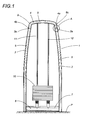
- Fig. 1 shows a frame for exercise machines in accordance with the present invention and in a schematic front view;
- Fig. 2 shows a section of an upright of the frame of Fig. 1 and in enlarged scale;
- Fig. 3 shows a detail A in enlarged scale referred to Fig. 1 and in a front view with some parts removed the better to highlight others.
- In accordance with the figures of the accompanying drawings, and with particular reference to Fig. 1, the
frame 1 in question is part of an isotonic exercise machine, which machine is not shown herein with reference to its other accessory parts, since they are known and not comprised in the invention. - The
frame 1 comprises a pair ofuprights upper cross member 4, and, in correspondence with a respective lower end, by alower cross member 6. - It should be noted that the
uprights uprights cross member 4, have outwardly concave development. In particular, theframe 1 is symmetrical with respect to an axis (not shown) that is substantially vertical and equidistant from theuprights - Inside the portal, which presents an inverted "U" shape, are installed two
vertical bars weight pack 10, able to slide and with adjustable mass. Thisweight pack 10 is able to slide, in the two directions, on thevertical bars frame 1. In Fig. 1, theweight pack 10 is positioned in the lower part of the frame, but it can be positioned at different heights with respect to a treadable plane P, without any loss of originality in the present description. - The
uprights upper cross member 4 are realized with a respective firsttubular bar 5 with rounded cross section, similar to a flattened circular section. Without detracting from the originality of the present description, the section of the firsttubular bar 5 can be defined as oval. - Fig. 1 also shows, to complete the
frame 1, alower cross member 6, bilaterally connected to the pair ofuprights tubular bar 7 with oval section geometrically similar to the firsttubular bar 5. In particular, without detracting from the general nature of the present description, this secondtubular bar 7 presents an essentially identical cross section to that of the firsttubular bar 5. - As can also be observed in Fig. 1, the pair of
uprights upper cross member 4 can be obtained in a single type of tubular cross member with oval/elliptical cross section, i.e. these elements are obtained from the same base section bar. - The architecture of the
uprights frame 1 is assembled, and theupper cross member 4 is also arched: in this way a portal is created that is shaped as an upside down "U" with rounded edges, closed at the bottom by thelower cross member 6. - As is well known, each isotonic machine is designed with the purpose of training a determined muscle district; hence, the vertical extension of the
uprights uprights uprights cross member 4 may be proportioned accordingly. - Fig. 3 shows that between the
extremities upper cross member 4 and the respectiveupper extremities uprights junctions 9 of theupper cross member 4 with the pair ofuprights - By way of example, these rapid coupling means 8 may be constituted by a bayonet coupling device comprising a plurality of
retractable teeth 20 positioned on arelated end section 21 realized on thecorresponding extremity upper cross member 4 and presenting smaller size with respect to the size of thecorresponding extremity uprights uprights internal projections 22 present on theuprights teeth 20 during the insertion of thecross member 4 and a subsequent stop against the teeth themselves, in the advanced position, upon completion of the coupling operation. It is possible to provide for the reversibility of the coupling described above by providing a control system (which can be activated from the exterior and is not shown herein) able to allow theteeth 20 to move inward in thesection 21 thereby freeing thecross member 4 from theuprights frame 1 is equivalent to a frame obtained by bending with variable radius from a single tubular bar with oval section. In this way thejunctions 9 would be realized automatically during the bending operation itself. - In an alternative solution, the "portal"
frame 1, that is theuprights upper cross member 4, could be realized as a whole starting from a single tubular bar (having an oval cross section) which is bent in correspondence of the curved portions indicated with thereference 9c. - We have described the section of the frame profile as oval, generalizing with this definition the possibility that it be derived from a flattened circular section.
- The oval shape (which could also be defined by an ellipse) is preferentially definable as per Fig. 2, in which the greater and respectively smaller axes X, Y define the values of length L and width H. Fig. 2 also shows three values of radius of curvature that realize, in their combination, the resulting oval combination: these radii are R1, the smallest, R2 the intermediate one and R3 the largest.
- Preferred values of the aforesaid dimensions, according to ratios therebetween, are:
- L/H = 2;
- R1/R3 = 0.168;
- R2/R3 = 0.39;
- L/R1 = 5.58.
-
- Based on such ratio values, it will therefore be possible to define a series or a family of mutually similar oval figures.
- By way of non-limiting further example, the following dimensions have been chosen in accompanying Fig. 3:
- L = 120 mm;
- H = 60 mm;
- R1 = 21.5 mm;
- R2 = 50 mm;
- R3 = 128 mm.
-
- It should be stressed that, still in regard to the values of the dimensions of the section of the
tubular bar 5, the thickness S of the tubular bar itself can lie within a range of values from 1 to 4 mm, and it preferably shall be 2.5 mm. - The Applicant has been able to verify that the
frame 1 thus obtained determines considerable practical and structural advantages on isotonic exercise machines. - In regard to the thickness and shape of the
uprights frame 1 allows to reduce the specific weight of the structure (computed on the basis of the length of the axis of the tubular elements) maintaining at least unchanged the mechanical resistance of the structure to the loads oriented according to the direction of elongation of the oval section itself. Thus theframe 1 presents greater rigidity than a quadrangular section of substantially identical weight (and thus presenting greater thickness). Maintaining constant the specific weight computed with respect to the length of the tubular bars and increasing the internal volumes to theuprights frames 1 that are less bulky and free of stiffening arms. These machines are thus easy to move and safer, presenting fewer projections and hindrances to the users' access. - The gradual variation of the curvature radii of the sections of the cross members and of the axes of the
uprights - It should be remembered that, since the section of the
uprights cross members - Considering the
frame 1 from the constructive standpoint as a plurality of individual lengths mutually connected in a rigid manner (and also because of the reduced value of thickness of theuprights cross members 4 and 6), in theframe 1 the geometric axes of the adjacent lengths of tube will substantially coincide with the axis of transmission of the stress acting under load. Since the stresses that the adjacent lengths transmit to each other are substantially normal stresses, the frames will be particularly well balanced under load thanks to the substantial absence of transverse loads. - It should also be noted that on the low thickness, the normal and geometric stress axis will also substantially coincide also in the welded lengths; hence, the stress response of the welded junctions will be considerably more gradual, since stress distribution is evenly distributed.
- Moreover, the large inner section of the tubular bars, obtained with the oval/elliptical conformation, allows conveniently to house accessory elements, such as electrical wires, driving cables, pulleys, etc., without having to occupy space outside the frame. The internal positioning of these accessories allows to simplify the structure of the machine and to make it easily accessible to the user without his/her having to walk over metal or electrical cables.
- The particular curvature of the uprights and of the cross member allows, in addition to a low deformation of the structure during use, also the elimination of accentuated narrowing in the junction areas of the elements (noted in traditional frames) which did not allow the normal passage of the accessories.
- The possible reversible coupling of the upper cross member allows to obtain an easier access to the interior part of the tubular bars comprising the frame for any ordinary or extraordinary maintenance operations.
- The invention thus conceived can be subject to numerous modifications and variations, without thereby departing from the scope of the inventive concept according to the claims. Moreover, all components can be replaced with technically equivalent elements.
- For instance, the same results can be obtained replacing the oval tubular bar used to realize the constructive elements of the
frame 1 with a tube of elliptical cross section.
Claims (23)
- Frame for exercise machines, frame (1) of the type comprising, among other elements, at least a pair of uprights (2, 3) and an upper cross member (4), mutually associated to define a portal, characterized in that at least said pair of uprights (2, 3) and said upper cross member (4) are realized with a respective first tubular bar (5) with substantially oval cross section.
- Frame according to claim 1, characterized in that said pair of uprights (2, 3) and said upper cross member (4), are realized as a whole starting from a single tubular bar.
- Frame according to claim 1 or 2, characterized in that said pair of uprights (2, 3) and said upper cross member (4) are realized with a first tubular bar (5) with elliptical cross section.
- Frame according to claim 1 or 2, presenting a lower cross member (6) associated to said pair of uprights (2, 3), characterized in that said lower cross member (6) is realized with a second tubular bar (7) with substantially oval cross section.
- Frame according to claim 4, characterized in that said lower cross member (6) is realized with a second tubular bar (7) with elliptical cross section.
- Frame according to claim 1, characterized in that at least between the extremities (4a, 4b) of said upper cross member (4) and the respective lower extremities (2a, 3a) of said pair of uprights (2, 3) means (8) are provided for the rapid coupling of said upper cross member (4) with said pair of uprights (2, 3).
- Frame according to claim 1, characterized in that at least between the extremities (4a, 4b) of said upper cross member (4) and the respective upper extremities (2a, 3a) of said pair of uprights (2, 3) means (8) are provided for the rapid coupling, by snapping, of said upper cross member (4) with said pair of uprights (2, 3).
- Frame according to claim 1 or 2, characterized in that each said first tubular bar (5) presents its oval cross section defined by geometric dimensions comprising two greater and respectively smaller axes (X, Y) of the same oval and able to define a value of length (L) and of width (H), and by three values of radius of curvature (R1, R2, R3), respectively smallest (R1), intermediate (R2), and greatest (R3), able to realize, in their combination, a resulting oval section; said geometric dimensions (L, H, R1, R2, R3) presenting mutual ratio values respectively of:L/H = 2;R1/R3 = 0.168;R2/R3 = 0.39;L/R1 = 5.58.
- Frame according to claim 1 or 2, characterized in that each said first tubular bar (5) presents a thickness (S) ranging between 1 and 4 mm.
- Frame according to claim 9, characterized in that each said tubular bar (5) presents said thickness (S) equal to 2.5 mm.
- Frame according to claim 4, characterized in that each said second tubular bar (7) presents its own oval cross section defined by geometric dimensions comprising two respectively greater and smaller axes (X, Y) of the same oval and able to define a value of length (L) and of width (H), and by three values of radius of curvature (R1, R2, R3), respectively smallest (R1), intermediate (R2), and greatest (R3), able to realize, in their combination, a resulting oval section; said geometric dimensions (L, H, R1, R2, R3) presenting mutual ratio values respectively of:L/H = 2;R1/R3 = 0.168;R2/R3 = 0.39;L/R1 = 5.58.
- Frame according to claim 4, characterized in that each said second tubular bar (7) presents a thickness (S) ranging between 1 and 4 mm.
- Frame according to claim 12, characterized in that each said second tubular bar (7) presents said thickness (S) equal to 2.5 mm.
- Frame according to claim 1, characterized in that said first tubular bar (5) with oval cross section is the same for said pair of uprights (2, 3) and for said upper cross member (4), i.e. being obtained from a same basic section bar.
- Frame according to claim 1 or 2, characterized in that each said upright (2, 3) presents an arched and mutually opposite development, when the frame (1) is mounted.
- Frame according to claim 1 or 2, characterized in that said upper cross member (4) presents an arched development.
- Frame according to claim 1 or 2, characterized in that each said upright (2, 3) and said upper cross member (4) present an arched development.
- Frame according to claim 1 or 2, characterized in that each said upright (2, 3) and said upper cross member (4) present an arched and outwardly concave development.
- Method for the realization of frames (1) for exercise machines, characterized in that a single tubular element (5) with oval profile is used to define a pair of uprights (2, 3) and at least one upper cross member (4) mutually assembled to define a portal with arched sides.
- Method according to claim 19, characterized in that_said upper cross member (4) is associated to said pair of uprights (2, 3) by means of snap coupling.
- Method according to claim 20, characterized in that said upper cross member (4) is associated to said pair of uprights (2, 3) by means of reversible snap coupling.
- Section bar for the realization of frames (1) for exercise machines, frame (1) of the type comprising at least a pair of uprights (2, 3) and an upper cross member (4), mutually associated to define a portal, characterized in that said section bar (5) is the same for said pair of uprights (2, 3) and for said upper cross member (4) and presents an oval cross section.
- Section bar according to claim 22, characterized in that said single type of section bar (5) presents an elliptical cross section.
Applications Claiming Priority (2)
| Application Number | Priority Date | Filing Date | Title |
|---|---|---|---|
| ITBO980375 | 1998-06-16 | ||
| IT1998BO000375A IT1304009B1 (en) | 1998-06-16 | 1998-06-16 | FRAME FOR GINNIC MACHINES. |
Publications (2)
| Publication Number | Publication Date |
|---|---|
| EP0965365A2 true EP0965365A2 (en) | 1999-12-22 |
| EP0965365A3 EP0965365A3 (en) | 2000-05-31 |
Family
ID=11343247
Family Applications (1)
| Application Number | Title | Priority Date | Filing Date |
|---|---|---|---|
| EP99830362A Withdrawn EP0965365A3 (en) | 1998-06-16 | 1999-06-11 | Frame for exercise machines |
Country Status (2)
| Country | Link |
|---|---|
| EP (1) | EP0965365A3 (en) |
| IT (1) | IT1304009B1 (en) |
Cited By (1)
| Publication number | Priority date | Publication date | Assignee | Title |
|---|---|---|---|---|
| WO2004014493A1 (en) * | 2002-07-28 | 2004-02-19 | Sonja Stromberg | Profile for frames of fitness and health machines |
Family Cites Families (6)
| Publication number | Priority date | Publication date | Assignee | Title |
|---|---|---|---|---|
| DE1927580A1 (en) * | 1969-05-30 | 1970-11-19 | Velox Werke Herbert Schnelle | Furniture with frames made of hollow profile |
| US5622527A (en) * | 1986-05-08 | 1997-04-22 | Proform Fitness Products, Inc. | Independent action stepper |
| DE3931478C1 (en) * | 1989-09-21 | 1991-04-04 | Deutsche Forschungsanstalt Fuer Luft- Und Raumfahrt Ev, 5300 Bonn, De | Triangular tubular frame - is made of circular or elliptical section plastics tubes fastened together |
| GB9023652D0 (en) * | 1990-10-31 | 1990-12-12 | Calvert Philip | Improvements in or relating to exercise apparatus |
| US5727764A (en) * | 1996-03-22 | 1998-03-17 | Lifegear, Inc. | Self-locking quick release bracket |
| US5716304A (en) * | 1996-05-07 | 1998-02-10 | Greenmaster Industrial Corp. | Elliptical frame structure for exercise bikes |
-
1998
- 1998-06-16 IT IT1998BO000375A patent/IT1304009B1/en active
-
1999
- 1999-06-11 EP EP99830362A patent/EP0965365A3/en not_active Withdrawn
Non-Patent Citations (1)
| Title |
|---|
| None |
Cited By (1)
| Publication number | Priority date | Publication date | Assignee | Title |
|---|---|---|---|---|
| WO2004014493A1 (en) * | 2002-07-28 | 2004-02-19 | Sonja Stromberg | Profile for frames of fitness and health machines |
Also Published As
| Publication number | Publication date |
|---|---|
| ITBO980375A1 (en) | 1999-12-16 |
| EP0965365A3 (en) | 2000-05-31 |
| IT1304009B1 (en) | 2001-03-02 |
Similar Documents
| Publication | Publication Date | Title |
|---|---|---|
| US9114273B2 (en) | Exercise device | |
| US4993706A (en) | Exercise bench | |
| EP2149392A1 (en) | Exercising device with combined stepping and twisting functions | |
| US20030060345A1 (en) | Weight systems for exercise equipment | |
| EP0965365A2 (en) | Frame for exercise machines | |
| US6558300B2 (en) | Weight stack for exercise machine | |
| US4883145A (en) | Ergonomic aerial basket | |
| JPH0226572A (en) | Body training machine for training muscle | |
| CN211705748U (en) | Multifunctional fitness equipment | |
| CN212214498U (en) | Stretching device of rhythm machine | |
| CN209556910U (en) | A kind of wire pole climbing ladder | |
| ITTO980046U1 (en) | GYM EXERCISE EQUIPMENT. | |
| CN213912129U (en) | Multifunctional single-station trainer | |
| CN212347585U (en) | Gymnastics auxiliary machinery | |
| CN214479123U (en) | Combined labor-saving cable pendant | |
| CN210551118U (en) | Material taking frame and new energy vehicle production line comprising same | |
| CN216436643U (en) | Groove type cable bridge wiring auxiliary device | |
| CN210873956U (en) | Arm strength stretching training device | |
| CN213096549U (en) | Umbrella opening device | |
| RU122028U1 (en) | TRAINING SIMULATOR MULTI-FUNCTIONAL | |
| CN201029665Y (en) | Mosquito net with sliding rail | |
| RU39279U1 (en) | SIMULATOR FOR TRAINING MUSCLES AND JOINTS | |
| US3378979A (en) | Mountable latticework | |
| CN114007704A (en) | Suspended mounting and exercise device and method of use | |
| EP0479797A1 (en) | Extension ladder. |
Legal Events
| Date | Code | Title | Description |
|---|---|---|---|
| PUAI | Public reference made under article 153(3) epc to a published international application that has entered the european phase |
Free format text: ORIGINAL CODE: 0009012 |
|
| AK | Designated contracting states |
Kind code of ref document: A2 Designated state(s): BE CH DE ES FR GB IT LI LU NL |
|
| AX | Request for extension of the european patent |
Free format text: AL;LT;LV;MK;RO;SI |
|
| PUAL | Search report despatched |
Free format text: ORIGINAL CODE: 0009013 |
|
| AK | Designated contracting states |
Kind code of ref document: A3 Designated state(s): AT BE CH CY DE DK ES FI FR GB GR IE IT LI LU MC NL PT SE |
|
| AX | Request for extension of the european patent |
Free format text: AL;LT;LV;MK;RO;SI |
|
| RIC1 | Information provided on ipc code assigned before grant |
Free format text: 7A 63B 21/062 A |
|
| RIN1 | Information on inventor provided before grant (corrected) |
Inventor name: CAMELLI, MARCO Inventor name: ALESSANDRI, NERIO |
|
| 17P | Request for examination filed |
Effective date: 20001122 |
|
| AKX | Designation fees paid |
Free format text: BE CH DE ES FR GB IT LI LU NL |
|
| 17Q | First examination report despatched |
Effective date: 20031209 |
|
| STAA | Information on the status of an ep patent application or granted ep patent |
Free format text: STATUS: THE APPLICATION IS DEEMED TO BE WITHDRAWN |
|
| 18D | Application deemed to be withdrawn |
Effective date: 20040420 |