EP1820561A1 - Diesel particulate filter comprising a catalytic layer - Google Patents
Diesel particulate filter comprising a catalytic layer Download PDFInfo
- Publication number
- EP1820561A1 EP1820561A1 EP07101480A EP07101480A EP1820561A1 EP 1820561 A1 EP1820561 A1 EP 1820561A1 EP 07101480 A EP07101480 A EP 07101480A EP 07101480 A EP07101480 A EP 07101480A EP 1820561 A1 EP1820561 A1 EP 1820561A1
- Authority
- EP
- European Patent Office
- Prior art keywords
- mass
- alumina
- composite oxide
- exhaust gas
- loading
- Prior art date
- Legal status (The legal status is an assumption and is not a legal conclusion. Google has not performed a legal analysis and makes no representation as to the accuracy of the status listed.)
- Granted
Links
- 230000003197 catalytic effect Effects 0.000 title description 19
- 239000002131 composite material Substances 0.000 claims abstract description 92
- PNEYBMLMFCGWSK-UHFFFAOYSA-N aluminium oxide Inorganic materials [O-2].[O-2].[O-2].[Al+3].[Al+3] PNEYBMLMFCGWSK-UHFFFAOYSA-N 0.000 claims abstract description 79
- 239000003054 catalyst Substances 0.000 claims abstract description 33
- 229910052784 alkaline earth metal Inorganic materials 0.000 claims abstract description 13
- 229910052761 rare earth metal Inorganic materials 0.000 claims abstract description 12
- 150000002910 rare earth metals Chemical class 0.000 claims abstract description 12
- 230000001737 promoting effect Effects 0.000 claims abstract description 4
- 229910052772 Samarium Inorganic materials 0.000 claims description 3
- 229910052688 Gadolinium Inorganic materials 0.000 claims description 2
- 229910052788 barium Inorganic materials 0.000 claims description 2
- 229910052791 calcium Inorganic materials 0.000 claims description 2
- 229910052749 magnesium Inorganic materials 0.000 claims description 2
- 229910052712 strontium Inorganic materials 0.000 claims description 2
- BASFCYQUMIYNBI-UHFFFAOYSA-N platinum Chemical compound [Pt] BASFCYQUMIYNBI-UHFFFAOYSA-N 0.000 description 178
- 239000007789 gas Substances 0.000 description 91
- 238000000746 purification Methods 0.000 description 44
- KDLHZDBZIXYQEI-UHFFFAOYSA-N Palladium Chemical compound [Pd] KDLHZDBZIXYQEI-UHFFFAOYSA-N 0.000 description 43
- OKTJSMMVPCPJKN-UHFFFAOYSA-N Carbon Chemical compound [C] OKTJSMMVPCPJKN-UHFFFAOYSA-N 0.000 description 40
- 229910052799 carbon Inorganic materials 0.000 description 40
- UGFAIRIUMAVXCW-UHFFFAOYSA-N Carbon monoxide Chemical compound [O+]#[C-] UGFAIRIUMAVXCW-UHFFFAOYSA-N 0.000 description 38
- 229910002091 carbon monoxide Inorganic materials 0.000 description 38
- 229930195733 hydrocarbon Natural products 0.000 description 37
- 150000002430 hydrocarbons Chemical class 0.000 description 37
- 230000001965 increasing effect Effects 0.000 description 36
- 229910052593 corundum Inorganic materials 0.000 description 34
- 229910001845 yogo sapphire Inorganic materials 0.000 description 34
- 238000011156 evaluation Methods 0.000 description 14
- 239000002245 particle Substances 0.000 description 14
- MCMNRKCIXSYSNV-UHFFFAOYSA-N Zirconium dioxide Chemical compound O=[Zr]=O MCMNRKCIXSYSNV-UHFFFAOYSA-N 0.000 description 12
- 230000003647 oxidation Effects 0.000 description 10
- 238000007254 oxidation reaction Methods 0.000 description 10
- 101100224414 Caenorhabditis elegans dpf-1 gene Proteins 0.000 description 9
- GWGQWFHTAOMUBD-UHFFFAOYSA-N [[3-[bis(phosphonomethyl)amino]-2-hydroxypropyl]-(phosphonomethyl)amino]methylphosphonic acid Chemical compound OP(=O)(O)CN(CP(O)(O)=O)CC(O)CN(CP(O)(O)=O)CP(O)(O)=O GWGQWFHTAOMUBD-UHFFFAOYSA-N 0.000 description 9
- 239000001301 oxygen Substances 0.000 description 9
- 229910052760 oxygen Inorganic materials 0.000 description 9
- QVGXLLKOCUKJST-UHFFFAOYSA-N atomic oxygen Chemical compound [O] QVGXLLKOCUKJST-UHFFFAOYSA-N 0.000 description 8
- 238000006243 chemical reaction Methods 0.000 description 8
- 239000000446 fuel Substances 0.000 description 8
- 229910052751 metal Inorganic materials 0.000 description 8
- 239000002184 metal Substances 0.000 description 8
- 238000011144 upstream manufacturing Methods 0.000 description 8
- 230000003247 decreasing effect Effects 0.000 description 7
- 239000011148 porous material Substances 0.000 description 5
- 239000000843 powder Substances 0.000 description 5
- CETPSERCERDGAM-UHFFFAOYSA-N ceric oxide Chemical compound O=[Ce]=O CETPSERCERDGAM-UHFFFAOYSA-N 0.000 description 4
- RCFVMJKOEJFGTM-UHFFFAOYSA-N cerium zirconium Chemical compound [Zr].[Ce] RCFVMJKOEJFGTM-UHFFFAOYSA-N 0.000 description 4
- 229910000422 cerium(IV) oxide Inorganic materials 0.000 description 4
- 238000010304 firing Methods 0.000 description 4
- 239000000463 material Substances 0.000 description 4
- 239000000203 mixture Substances 0.000 description 4
- HBMJWWWQQXIZIP-UHFFFAOYSA-N silicon carbide Chemical compound [Si+]#[C-] HBMJWWWQQXIZIP-UHFFFAOYSA-N 0.000 description 4
- 239000002002 slurry Substances 0.000 description 4
- XLYOFNOQVPJJNP-UHFFFAOYSA-N water Substances O XLYOFNOQVPJJNP-UHFFFAOYSA-N 0.000 description 4
- 238000005259 measurement Methods 0.000 description 3
- 238000000034 method Methods 0.000 description 3
- 229910052763 palladium Inorganic materials 0.000 description 3
- 238000005192 partition Methods 0.000 description 3
- 229910052697 platinum Inorganic materials 0.000 description 3
- 229910010271 silicon carbide Inorganic materials 0.000 description 3
- IJGRMHOSHXDMSA-UHFFFAOYSA-N Atomic nitrogen Chemical compound N#N IJGRMHOSHXDMSA-UHFFFAOYSA-N 0.000 description 2
- 229910052684 Cerium Inorganic materials 0.000 description 2
- 239000011230 binding agent Substances 0.000 description 2
- 238000000975 co-precipitation Methods 0.000 description 2
- 229910052878 cordierite Inorganic materials 0.000 description 2
- 230000006866 deterioration Effects 0.000 description 2
- 238000010586 diagram Methods 0.000 description 2
- JSKIRARMQDRGJZ-UHFFFAOYSA-N dimagnesium dioxido-bis[(1-oxido-3-oxo-2,4,6,8,9-pentaoxa-1,3-disila-5,7-dialuminabicyclo[3.3.1]nonan-7-yl)oxy]silane Chemical compound [Mg++].[Mg++].[O-][Si]([O-])(O[Al]1O[Al]2O[Si](=O)O[Si]([O-])(O1)O2)O[Al]1O[Al]2O[Si](=O)O[Si]([O-])(O1)O2 JSKIRARMQDRGJZ-UHFFFAOYSA-N 0.000 description 2
- 229910001873 dinitrogen Inorganic materials 0.000 description 2
- 230000000694 effects Effects 0.000 description 2
- 230000002708 enhancing effect Effects 0.000 description 2
- CMIHHWBVHJVIGI-UHFFFAOYSA-N gadolinium(III) oxide Inorganic materials [O-2].[O-2].[O-2].[Gd+3].[Gd+3] CMIHHWBVHJVIGI-UHFFFAOYSA-N 0.000 description 2
- 238000005342 ion exchange Methods 0.000 description 2
- 239000002923 metal particle Substances 0.000 description 2
- -1 oxygen ions Chemical class 0.000 description 2
- 230000008929 regeneration Effects 0.000 description 2
- 238000011069 regeneration method Methods 0.000 description 2
- FKTOIHSPIPYAPE-UHFFFAOYSA-N samarium(III) oxide Inorganic materials [O-2].[O-2].[O-2].[Sm+3].[Sm+3] FKTOIHSPIPYAPE-UHFFFAOYSA-N 0.000 description 2
- 229910052581 Si3N4 Inorganic materials 0.000 description 1
- 229910052783 alkali metal Inorganic materials 0.000 description 1
- 150000001340 alkali metals Chemical class 0.000 description 1
- 229910010293 ceramic material Inorganic materials 0.000 description 1
- 239000007800 oxidant agent Substances 0.000 description 1
- 239000013618 particulate matter Substances 0.000 description 1
- NWAHZABTSDUXMJ-UHFFFAOYSA-N platinum(2+);dinitrate Chemical compound [Pt+2].[O-][N+]([O-])=O.[O-][N+]([O-])=O NWAHZABTSDUXMJ-UHFFFAOYSA-N 0.000 description 1
- 230000001172 regenerating effect Effects 0.000 description 1
- 239000000126 substance Substances 0.000 description 1
- 229910052726 zirconium Inorganic materials 0.000 description 1
Images


Classifications
-
- B—PERFORMING OPERATIONS; TRANSPORTING
- B01—PHYSICAL OR CHEMICAL PROCESSES OR APPARATUS IN GENERAL
- B01D—SEPARATION
- B01D53/00—Separation of gases or vapours; Recovering vapours of volatile solvents from gases; Chemical or biological purification of waste gases, e.g. engine exhaust gases, smoke, fumes, flue gases, aerosols
- B01D53/34—Chemical or biological purification of waste gases
- B01D53/92—Chemical or biological purification of waste gases of engine exhaust gases
- B01D53/94—Chemical or biological purification of waste gases of engine exhaust gases by catalytic processes
- B01D53/944—Simultaneously removing carbon monoxide, hydrocarbons or carbon making use of oxidation catalysts
-
- B—PERFORMING OPERATIONS; TRANSPORTING
- B01—PHYSICAL OR CHEMICAL PROCESSES OR APPARATUS IN GENERAL
- B01D—SEPARATION
- B01D53/00—Separation of gases or vapours; Recovering vapours of volatile solvents from gases; Chemical or biological purification of waste gases, e.g. engine exhaust gases, smoke, fumes, flue gases, aerosols
- B01D53/34—Chemical or biological purification of waste gases
- B01D53/92—Chemical or biological purification of waste gases of engine exhaust gases
- B01D53/94—Chemical or biological purification of waste gases of engine exhaust gases by catalytic processes
- B01D53/9445—Simultaneously removing carbon monoxide, hydrocarbons or nitrogen oxides making use of three-way catalysts [TWC] or four-way-catalysts [FWC]
- B01D53/945—Simultaneously removing carbon monoxide, hydrocarbons or nitrogen oxides making use of three-way catalysts [TWC] or four-way-catalysts [FWC] characterised by a specific catalyst
-
- B—PERFORMING OPERATIONS; TRANSPORTING
- B01—PHYSICAL OR CHEMICAL PROCESSES OR APPARATUS IN GENERAL
- B01J—CHEMICAL OR PHYSICAL PROCESSES, e.g. CATALYSIS OR COLLOID CHEMISTRY; THEIR RELEVANT APPARATUS
- B01J23/00—Catalysts comprising metals or metal oxides or hydroxides, not provided for in group B01J21/00
- B01J23/002—Mixed oxides other than spinels, e.g. perovskite
-
- B—PERFORMING OPERATIONS; TRANSPORTING
- B01—PHYSICAL OR CHEMICAL PROCESSES OR APPARATUS IN GENERAL
- B01J—CHEMICAL OR PHYSICAL PROCESSES, e.g. CATALYSIS OR COLLOID CHEMISTRY; THEIR RELEVANT APPARATUS
- B01J23/00—Catalysts comprising metals or metal oxides or hydroxides, not provided for in group B01J21/00
- B01J23/38—Catalysts comprising metals or metal oxides or hydroxides, not provided for in group B01J21/00 of noble metals
- B01J23/54—Catalysts comprising metals or metal oxides or hydroxides, not provided for in group B01J21/00 of noble metals combined with metals, oxides or hydroxides provided for in groups B01J23/02 - B01J23/36
- B01J23/56—Platinum group metals
- B01J23/63—Platinum group metals with rare earths or actinides
-
- B01J35/56—
-
- B—PERFORMING OPERATIONS; TRANSPORTING
- B01—PHYSICAL OR CHEMICAL PROCESSES OR APPARATUS IN GENERAL
- B01D—SEPARATION
- B01D2255/00—Catalysts
- B01D2255/10—Noble metals or compounds thereof
- B01D2255/102—Platinum group metals
-
- B—PERFORMING OPERATIONS; TRANSPORTING
- B01—PHYSICAL OR CHEMICAL PROCESSES OR APPARATUS IN GENERAL
- B01D—SEPARATION
- B01D2255/00—Catalysts
- B01D2255/20—Metals or compounds thereof
- B01D2255/204—Alkaline earth metals
-
- B—PERFORMING OPERATIONS; TRANSPORTING
- B01—PHYSICAL OR CHEMICAL PROCESSES OR APPARATUS IN GENERAL
- B01D—SEPARATION
- B01D2255/00—Catalysts
- B01D2255/20—Metals or compounds thereof
- B01D2255/206—Rare earth metals
-
- B—PERFORMING OPERATIONS; TRANSPORTING
- B01—PHYSICAL OR CHEMICAL PROCESSES OR APPARATUS IN GENERAL
- B01J—CHEMICAL OR PHYSICAL PROCESSES, e.g. CATALYSIS OR COLLOID CHEMISTRY; THEIR RELEVANT APPARATUS
- B01J23/00—Catalysts comprising metals or metal oxides or hydroxides, not provided for in group B01J21/00
- B01J23/10—Catalysts comprising metals or metal oxides or hydroxides, not provided for in group B01J21/00 of rare earths
-
- B—PERFORMING OPERATIONS; TRANSPORTING
- B01—PHYSICAL OR CHEMICAL PROCESSES OR APPARATUS IN GENERAL
- B01J—CHEMICAL OR PHYSICAL PROCESSES, e.g. CATALYSIS OR COLLOID CHEMISTRY; THEIR RELEVANT APPARATUS
- B01J2523/00—Constitutive chemical elements of heterogeneous catalysts
-
- F—MECHANICAL ENGINEERING; LIGHTING; HEATING; WEAPONS; BLASTING
- F01—MACHINES OR ENGINES IN GENERAL; ENGINE PLANTS IN GENERAL; STEAM ENGINES
- F01N—GAS-FLOW SILENCERS OR EXHAUST APPARATUS FOR MACHINES OR ENGINES IN GENERAL; GAS-FLOW SILENCERS OR EXHAUST APPARATUS FOR INTERNAL COMBUSTION ENGINES
- F01N3/00—Exhaust or silencing apparatus having means for purifying, rendering innocuous, or otherwise treating exhaust
- F01N3/02—Exhaust or silencing apparatus having means for purifying, rendering innocuous, or otherwise treating exhaust for cooling, or for removing solid constituents of, exhaust
- F01N3/021—Exhaust or silencing apparatus having means for purifying, rendering innocuous, or otherwise treating exhaust for cooling, or for removing solid constituents of, exhaust by means of filters
- F01N3/033—Exhaust or silencing apparatus having means for purifying, rendering innocuous, or otherwise treating exhaust for cooling, or for removing solid constituents of, exhaust by means of filters in combination with other devices
- F01N3/035—Exhaust or silencing apparatus having means for purifying, rendering innocuous, or otherwise treating exhaust for cooling, or for removing solid constituents of, exhaust by means of filters in combination with other devices with catalytic reactors, e.g. catalysed diesel particulate filters
-
- Y—GENERAL TAGGING OF NEW TECHNOLOGICAL DEVELOPMENTS; GENERAL TAGGING OF CROSS-SECTIONAL TECHNOLOGIES SPANNING OVER SEVERAL SECTIONS OF THE IPC; TECHNICAL SUBJECTS COVERED BY FORMER USPC CROSS-REFERENCE ART COLLECTIONS [XRACs] AND DIGESTS
- Y02—TECHNOLOGIES OR APPLICATIONS FOR MITIGATION OR ADAPTATION AGAINST CLIMATE CHANGE
- Y02T—CLIMATE CHANGE MITIGATION TECHNOLOGIES RELATED TO TRANSPORTATION
- Y02T10/00—Road transport of goods or passengers
- Y02T10/10—Internal combustion engine [ICE] based vehicles
- Y02T10/12—Improving ICE efficiencies
Definitions
- This invention relates to diesel particulate filters.
- a diesel particulate filter In order to prevent particulates (gas-borne particulate matter) contained in exhaust gas of a diesel engine from being emitted into the air, it is effective to fit a diesel particulate filter (DPF) in the exhaust pipe of the engine.
- the DPF is obtained by forming a heat-resistance ceramic material, such as silicon carbide (SiC) or cordierite, in a three-dimensional network structure or a wall-through honeycomb structure. Particulates in exhaust gas are trapped by the DPF during the passage of the exhaust gas through the DPF.
- the DPF has a catalyst layer coated on the wall surfaces of exhaust gas channels in the DPF.
- 2003-334443 discloses that a mixture of cerium-zirconium (Ce-Zr) composite oxide and ⁇ -alumina is loaded on a monolith support and platinum (Pt) is loaded on the mixture at 2g per 1 L of the monolith support.
- Ce-Zr cerium-zirconium
- Pt platinum
- Ce-Zr composite oxide is effective in increasing the particulate burning rate under low-temperature conditions, there is a demand in the art to further increase the particulate burning rate to burn off particulates more efficiently.
- unburned components in exhaust gas such as hydrocarbons (HC) and carbon monoxide (CO) are converted by a catalyst disposed upstream of the DPF.
- HC hydrocarbons
- CO carbon monoxide
- the particulate burning rate and the exhaust gas purification performance of the DPF can be enhanced by increasing the amount of catalytic metal loaded on the support material, such as a composite oxide as described above. However, if the amount of catalytic metal loaded on the support material is increased, the DPF becomes more expensive correspondingly.
- an object of the present invention is to enhance the particulate burning rate and the exhaust gas purification performance of the DPF while minimizing the amount of catalytic metal used.
- the inventor has found that a composite oxide containing Ce as a major component and rare earth metal other than Ce or alkali earth metal is effective in increasing the particulate burning rate and combining the composite oxide with alumina and Pt enhances the exhaust gas purification performance of the DPF concurrently, thereby completing the present invention.
- the present invention is directed to a diesel particulate filter disposed in an exhaust passage of a diesel engine and including a filter body for trapping particulates exhausted from the engine, walls forming exhaust gas channels in the filter body being coated with a catalyst layer for promoting the burning of the trapped particulates, and the diesel particulate filter is characterised in that the catalyst layer contains alumna and a composite oxide containing Ce as a major component and rare earth metal other than Ce or alkali earth metal and Pt is loaded on the alumina and the composite oxide.
- the particulate burning rate of the DPF increases and the exhaust gas purification performance thereof enhances.
- the reason why the particulate burning rate increases can be considered as follows.
- the areas around the firing points run short of oxygen.
- the composite oxide has a higher oxygen ionic conductivity than Ce-Zr composite oxide conventionally used, oxygen ions are likely to be efficiently and continuously supplied from high oxygen concentration sites via the composite oxide to the firing points. Therefore, it can be considered that once firing points are generated, particulates rapidly burn off even if the amount of Pt loaded as a catalyst is small.
- the catalyst layer contains a catalytic component obtained by loading Pt on alumina, the catalytic component efficiently converts HC and CO in exhaust gas by oxidation. Furthermore, as later shown by experimental data, the catalytic component acts to increase the particulate burning rate, combined with the Pt-loading composite oxide.
- the ratio of the amount of Pt loaded on the alumina to the total amount of Pt loaded on the composite oxide and Pt loaded on the alumina is preferably not less than 35 mass%.
- the catalytic component obtained by loading Pt on alumina is effective in enhancing the exhaust gas purification performance of the DPF.
- the ratio of the amount of Pt loaded on the alumina is preferably not less than 35 mass%, which surely enhances the exhaust gas purification performance of the DPF.
- the ratio of the amount of Pt loaded on the alumina is preferably not more than 90 mass%. Increasing the ratio of the amount of Pt loaded on the alumina is effective in enhancing the exhaust gas purification performance of the DPF. However, if the ratio is excessive, the amount of Pt to be loaded on the composite oxide becomes smaller correspondingly. Since the Pt-loading composite oxide greatly contributes to increasing the particulate burning rate, the ratio of the amount of Pt loaded on the alumina is preferably not more than 90 mass% in order to avoid decrease in the particulate burning rate.
- the ratio of the amount of Pt loaded on the alumina is more preferably between 50 mass% and 90 mass% both inclusive and still more preferably more than 50 mass%.
- palladium (Pd) is further loaded on the alumina on which Pt is loaded.
- Pd is inferior in heat resistance to Pt, this is not significant disadvantage.
- the reason for this is, as described above, that the combination of the Pt-loading composite oxide and the Pt-loading alumina increases the particulate burning rate and, therefore, particulates can be well burnt off without the need to increase the DPF temperature as conventionally done. In other words, since there is no need to increase the DPF temperature to a high temperature as conventionally done in order to burn off particulates, this avoids thermal deterioration of Pd. Therefore, Pd can be effectively used to enhance the exhaust gas purification performance under low-temperature conditions.
- the rare earth metal preferably comprises at least one selected from Sm and Gd, and the alkali earth metal preferably comprises at least one selected from Mg, Ca, Sr and Ba.
- the particulate burning rate of the DPF increases and the exhaust gas purification performance thereof enhances. This is advantageous in rapid regeneration and exhaust gas conversion of the DPF at relatively low temperatures, improves fuel efficiency and provides cost reduction of the DPF.
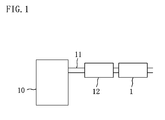
- the reference numeral 1 denotes a DPF disposed in an exhaust passage 11 of a diesel engine 10.
- An upstream catalyst 12 is disposed in the exhaust passage 11 upstream of the DPF 1 in the flow direction of exhaust gas.
- a NOx trap catalyst having oxidation catalytic function, an oxidation catalyst containing no NOx storage component or both can be disposed as the upstream catalyst 12.
- the NOx trap catalyst is obtained by loading, on a support material such as active alumina, a NOx storage component (such as an alkali earth metal, typically Ba, or an alkali metal) for absorbing NOx in the exhaust gas at high oxygen concentrations in the exhaust gas (at lean air-fuel ratios) and a catalytic metal, such as Pt, for reducing NOx released from the NOx storage component when the oxygen concentration in the exhaust gas drops (at stoichiometric or rich air-fuel ratios), and also acts as a catalyst for converting HC and CO to harmless substances by oxidation.
- a NOx storage component such as an alkali earth metal, typically Ba, or an alkali metal
- Pt catalytic metal
- the oxidation catalyst is obtained by loading a catalytic metal, such as Pt or Pd, on a support material such as active alumina and acts to oxidize HC and CO in the exhaust gas.
- a catalytic metal such as Pt or Pd
- a support material such as active alumina
- the DPF 1 has a honeycomb structure in which a large number of exhaust gas channels 2 and 3 run in parallel with each other.
- the DPF 1 has a structure in which a plurality of exhaust gas inflow channels 2 and a plurality of exhaust gas outflow channels 3 are alternately arranged vertically and horizontally.
- Each exhaust gas inflow channel 2 is closed at the downstream end by a plug 4, while each exhaust gas outflow channel 3 is closed at the upstream end by a plug 4.
- the adjacent exhaust gas inflow and outflow channels 2 and 3 are separated from each other by a thin partition wall 5.
- the hatched parts denote the plugs 4 at the upstream ends of the exhaust gas outflow channels 3.
- the body of the DPF 1 is formed of cordierite or an inorganic porous material, such as SiC, Si 3 N 4 or sialon.
- the exhaust gas flowing into each exhaust gas inflow channel 2 flows out through the surrounding partition walls 5 into the adjacent exhaust gas outflow channels 3, as shown in arrows in Figure 3. More specifically, as shown in Figure 4, each partition wall 5 is formed with micro pores (exhaust gas channels) 6 communicating the exhaust gas inflow channel 2 with the adjacent exhaust gas outflow channel 3 so that the exhaust gas flows through the micro pores 6. Particulates are trapped and deposited mainly on the wall surfaces of the exhaust gas inflow channels 2 and the micro pores 6.
- a catalyst layer 7 for promoting the burning of trapped particulates is coated on the walls of all the exhaust gas channels (i.e., exhaust gas inflow channels 2, exhaust gas outflow channels 3 and micro pores 6 ) in the body of the DPF 1.
- the catalyst layer 7 contains alumina and a composite oxide containing Ce as a major component and rare earth metal other than Ce or alkali earth metal and at least Pt is loaded as a catalytic metal on the alumina and the composite oxide.
- Figure 5 is a conceptual diagram showing the structure of components constituting the catalyst layer in the DPF 1 according to the present invention.
- the reference numeral 13 denotes a composite oxide particle contained in the catalyst layer and loading Pt particles
- the reference numeral 14 denotes an alumina particle contained in the catalyst layer and loading Pt particles and Pd particles.
- Some alumina particles 14 in the catalyst layer loads no Pd particles.
- the composite oxide particle 13 may load one or more other kinds of catalytic metal particles in addition to Pt particles and the alumina particle 14 may load one or more other kinds of catalytic metal particles in addition to Pt and Pd particles.
- Figure 6 shows results of measurement of carbon burning rates carried out in order to evaluate the diesel particulate burning rates of various kinds of oxides including composite oxides, in which the carbon burning rates of the oxides were measured instead of the diesel particulate burning rates.
- Samples for the evaluation were prepared as follows. First, a slurry was prepared by adding a ZrO 2 binder and ion-exchange water to each oxide on which Pt particles were loaded. The obtained slurry was coated on the wall surfaces of the exhaust gas channels in a SiC filter body of 25 mL capacity uniformly over the entire filter length. Then, the filter was calcined by keeping it at 500°C for two hours under atmospheric conditions. In loading Pt on each oxide, a solution of diamminedinitro platinum nitrate was used as a Pt source and an evaporation-to-dryness method was employed.
- each sample was aged by keeping it at 800°C for 24 hours under atmospheric conditions and 10g/L of carbon was then deposited on the catalyst layer of the sample.
- each sample was attached to a fixed-bed flow reactor and the internal temperature of the reactor was raised from room temperature at a rate of 15°C per minute with the sample in a flow of nitrogen gas containing 10 volume% of oxygen. Then, when the gas temperature reached 590°C, the carbon burning rate of the sample was determined by examining changes in CO concentration and CO 2 concentration in the gas having passed through the sample.
- Zr 0.63 Ce 0.37 O 2 is a Zr-Ce composite oxide containing Zr and Ce at a molar ratio of 63:37.
- Oxides including CeO 2 -8mol%MgO and listed below it are binary oxides containing Ce as a major component and one kind of alkali earth metal or rare earth metal, such as Mg, but not containing Zr.
- mol% means that, for example, in CeO 2 -8mol%MgO, the composite oxide contains 8% by mole of MgO with respect to its total molar quantity. All of these composite oxides were prepared by coprecipitation.
- the term "loaded Pt" described in the upper right corner of Figure 6 means the value showing the amount of Pt loaded per 1L of filter body.
- Figure 6 shows that the Zr-Ce composite oxide has a smaller carbon burning rate than ZrO 2 and CeO 2 that the binary oxides containing Ce as a major component and one kind of alkali earth metal or rare earth metal have much higher carbon burning rates than not only the Zr-Ce composite oxide but also ZrO 2 and CeO 2 , and particularly that though the amount of Pt loaded of each of the Zr-Ce composite oxide, ZrO 2 and CeO 2 was 2g/L, the composite oxides containing Ce as a major component have much higher carbon burning rates than the Zr-Ce composite oxide, ZrO 2 and CeO 2 even if they have a smaller amount of Pt loaded of 0.5g/L. It can be seen from this that the composite oxides used in the DPF according to the present invention are very useful in rapidly burning off particulates.
- the DPF of this embodiment employs as a composite oxide a binary oxide containing Ce and Sm but containing no Zr.
- the Ce-Sm composite oxide (CeSmO) contains 4 mol% of Sm 2 O 3 with respect to its total molar quantity and was prepared by coprecipitation.
- the method of producing the DPF is as follows.
- Powder of a Pt-loading CeSmO (Pt/CeSmO) obtained by loading Pt particles on a Ce-Sm composite oxide was mixed with powder of a Pt-loading Al 2 O 3 (Pt/Al 2 O 3 ) obtained by loading Pt particles on ⁇ -alumina and a ZrO 2 binder and ion-exchange water were added to the powder mixture to obtain a slurry.
- the obtained slurry was coated on the wall surfaces of exhaust gas channels in a SiC filter body of 25 mL capacity uniformly over the entire filter length and the filter was calcined by keeping it at 500°C for two hours under atmospheric conditions.
- an evaporation-to-dryness method was employed.
- a plurality of DPF samples were prepared that have different ratios of the amount of Pt loaded on ⁇ -alumina to the total amount of Pt loaded on the Ce-Sm composite oxide and ⁇ -alumina (hereinafter, referred to as the alumina-side Pt loading ratio) and each sample was measured in terms of exhaust gas purification performance and particulate burning rate.
- samples are of five types having a common amount of Pt/CeSmO powder loaded of 25g/L (wherein g/L means gram per I L of filter body; the same applies hereinafter), a common amount of Pt/Al 2 O 3 powder loaded of 25g/L, a common total amount of Pt in Pt/CeSmO and Pt/Al 2 O 3 (i.e., amount of Pt loaded on CeSmO and Al 2 O 3 ) of 0.5g/L and different alumina-side Pt loading ratios of 0 mass%, 25 mass%, 50 mass%, 75 mass% and 100 mass%.
- the amount of Pt in Pt/CeSmO is 0.125g/L and the amount of Pt in Pt/Al 2 O 3 is 0.375g/L.
- Each sample was aged by keeping it at 800°C for 24 hours under atmospheric conditions as described above and then subjected to a rig test to measure its T50 (°C) and C300 (%) that are indices for HC and CO conversion performance.
- the rig test was carried out by attaching each sample to a fixed bed flow reactor.
- the synthesized exhaust gas used had an A/F ratio of 28 and the following composition:
- T50 (°C) is the gas temperature at the inlet of the DPF when the concentration of each exhaust gas component (HC and CO) detected downstream of the DPF reaches half of that of the corresponding exhaust gas component flowing into the DPF (when the conversion efficiency reaches 50%) after the temperature of the synthesized exhaust gas is gradually increased (i.e., the light-off temperature), and indicates the low-temperature catalytic conversion performance of the DPF.
- C300 (%) is the catalytic conversion efficiency of each exhaust gas component (HC and CO) when the synthesized exhaust gas temperature at the DPF inlet is 300°C and indicates the high-temperature catalytic conversion performance of the DPF.
- T50 when the alumina-side Pt loading ratio increased from 0 to 25 mass%, both HC and CO exhibited slightly higher T50. As the alumina-side Pt loading ratio further increased, HC and CO gradually decreased T50.
- C300 when the alumina-side Pt loading ratio increased from 0 to 25 mass%, both HC and CO slightly decreased. As the alumina-side Pt loading ratio further increased, HC and CO gradually increased C300.
- the alumina-side Pt loading ratio is preferably not less than 35 mass%, and more preferably not less than 50 mass%.
- the carbon burning rate of each sample was determined, in the same manner as in the carbon burning rate measurement as described above with reference to Figure 6, in a flow of nitrogen gas containing 10 volume% of oxygen and 300 ppm of NO when the gas temperature reached 590°C. The results are as shown in Figure 8 .
- Figure 8 shows that as the alumina-side Pt loading ratio increased to 75 mass%, the carbon burning rate steadily increased but that when the alumina-side Pt loading ratio reached 100 mass%, the carbon burning rate became smaller than when it was 0 mass%. Therefore, it can be seen from the figure that in order to provide high particulate burning rates, the alumina-side Pt loading ratio is preferably not more than 90 mass%.
- a Pt additionally loading sample was prepared by additionally loading 0.5g/L of Pt on ⁇ -alumina loading 0.375g/L of Pt and a Pd additionally loading sample was prepared by additionally loading 0.3g/L of Pd on ⁇ -alumina loading 0.375g/L of Pt. Then, each of the obtained samples was subjected to an evaluation test for exhaust gas purification performance in the same manner as described above.
- the total amount of catalytic metal loaded of the Pt additionally loading sample was 1.0g/L and the total amount of catalytic metal loaded of the Pd additionally loading sample was 0.8g/L.
- the test results are shown in Table 1.
- Table 1 shows that when Pt was additionally loaded on ⁇ -alumina, both HC and CO exhibited better T50 performance and also shows that when Pd was additionally loaded on ⁇ -alumina, both HC and CO exhibited still better T50 performance. Furthermore, while the amount of Pt additionally loaded is 0.5g/L, the amount of Pd additionally loaded is 0.3g/L that is smaller than the former. Therefore, additionally loading Pd on ⁇ -alumina significantly improves the exhaust gas purification performance of the DPF.
- the DPF of this embodiment employs, instead of the Ce-Sm composite oxide in Embodiment 1, a Ce-Gd composite oxide (CeGdO) containing 4 mol% of Gd 2 O 3 and the other points are the same as in Embodiment 1.
- CeGdO Ce-Gd composite oxide
- five DPF samples were prepared that have different alumina-side Pt loading ratios of 0 mass%, 25 mass%, 50 mass%, 75 mass% and 100 mass%.
- a Pt additionally loading sample was prepared by additionally loading 0.5g/L of Pt on ⁇ -alumina and a Pd additionally loading sample was prepared by additionally loading 0.3g/L of Pd on ⁇ -alumina. Then, as in Embodiment 1, the above five samples were subjected to evaluation tests for exhaust gas purification performance and particulate burning rate and the Pt additionally loading sample and the Pd additionally loading sample were subjected to an evaluation test for exhaust gas purification performance. The test results are shown in Tables 2 and 3.
- Table 2 shows that also when the Ce-Gd composite oxide was used as a composite oxide, as in the case of using the Ce-Sm composite oxide in Embodiment 1, high exhaust gas purification performance was obtained and the particulate burning rate increased. Furthermore, as in Embodiment 1, the carbon burning rate gradually increased as the alumina-side Pt loading ratio increased, but it decreased when the alumina-side Pt loading ratio was excessive. On the other hand, the case of using the Ce-Gd composite oxide is slightly different from the case of using the Ce-Sm composite oxide in Embodiment 1 in that it did not deteriorate the exhaust gas purification performance at an alumina-side Pt loading ratio of 25 mass% and the exhaust gas purification performance gradually increased as the alumina-side Pt loading ratio increased.
- the alumina-side Pt loading ratio is preferably not less than 35 mass%.
- Table 3 shows that also in the case of using the Ce-Gd composite oxide, as in the case of using the Ce-Sm composite oxide in Embodiment 1, the Pd additionally loading DPF sample exhibited better T50 performance for HC and CO than the Pt additionally loading DPF sample.
- the DPF of this embodiment employs, instead of the Ce-Sm composite oxide in Embodiment 1, a Ce-Mg composite oxide (CeMgO) containing 8 mol% of MgO and the other points are the same as in Embodiment 1.
- CeMgO Ce-Mg composite oxide
- five DPF samples were prepared that have different alumina-side Pt loading ratios of 0 mass%, 25 mass%, 50 mass%, 75 mass% and 100 mass%.
- a Pt additionally loading sample was prepared by additionally loading 0.5g/L of Pt on ⁇ -alumina and a Pd additionally loading sample was prepared by additionally loading 0.3g/L of Pd on ⁇ -alumina. Then, as in Embodiment 1, the above five samples were subjected to evaluation tests for exhaust gas purification performance and particulate burning rate and the Pt additionally loading sample and the Pd additionally loading sample were subjected to an evaluation test for exhaust gas purification performance. The test results are shown in Tables 4 and 5.
- Table 4 shows that also when the Ce-Mg composite oxide was used as a composite oxide, high exhaust gas purification performance was obtained and the particulate burning rate increased. Furthermore, as in Embodiment 2, the exhaust gas purification performance and the carbon burning rate gradually enhanced as the alumina-side Pt loading ratio increased, but the carbon burning rate decreased when the alumina-side Pt loading ratio was excessive. In this case, when the alumina-side Pt loading ratio increased from 0 mass% to 25 mass%, both the exhaust gas purification performance and me carbon burning rate significantly enhanced. Therefore, the alumina-side Pt loading ratio is preferably not less than 25 mass%.
- Table 5 shows that also in the case of using the Ce-Mg composite oxide, as in the case of using the Ce-Sm composite oxide in Embodiment 1, the Pd additionally loading DPF sample exhibited better T50 performance for HC and CO than the Pt additionally loading DPF sample.
- the DPF of this embodiment employs, instead of the Ce-Sm composite oxide in Embodiment 1, a Ce-Ca composite oxide (CeCaO) containing 8 mol% of CaO and the other points are the same as in Embodiment 1.
- CeCaO Ce-Ca composite oxide
- five DPF samples were prepared that have different alumina-side Pt loading ratios of 0 mass%, 25 mass%, 50 mass%, 75 mass% and 100 mass%.
- a Pt additionally loading sample was prepared by additionally loading 0.5g/L of Pt on ⁇ -alumina and a Pd additionally loading sample was prepared by additionally loading 0.3g/L of Pd on ⁇ -alumina. Then, as in Embodiment 1, the above five samples were subjected to evaluation tests for exhaust gas purification performance and particulate burning rate and the Pt additionally loading sample and the Pd additionally loading sample were subjected to an evaluation test for exhaust gas purification performance. The test results are shown in Tables 6 and 7.
- Table 6 shows that also when the Ce-Ca composite oxide was used as a composite oxide, high exhaust gas purification performance was obtained and the particulate burning rate increased. Furthermore, as in Embodiment 2, the exhaust gas purification performance and the carbon burning rate gradually enhanced as the alumina-side Pt loading ratio increased, but the carbon burning rate decreased when the alumina-side Pt loading ratio was excessive. This case is characterized in that higher carbon burning rates were exhibited than in the former cases. Also in this case, when the alumina-side Pt loading ratio increased from 0 mass% to 25 mass%, both the exhaust gas purification performance and the carbon burning rate significantly enhanced. Therefore, the alumina-side Pt loading ratio is preferably not less than 25 mass%.
- Table 7 shows that also in the case of using the Ce-Ca composite oxide, as in the case of using the Ce-Sm composite oxide in Embodiment 1, the Pd additionally loading DPF sample exhibited better T50 performance for HC and CO than the Pt additionally loading DPF sample.
- the DPF of this embodiment employs, instead of the Ce-Sm composite oxide in Embodiment 1, a Ce-Sr composite oxide (CeSrO) containing 8 mol% of SrO and the other points are the same as in Embodiment 1.
- CeSrO Ce-Sr composite oxide
- five DPF samples were prepared that have different alumina-side Pt loading ratios of 0 mass%, 25 mass%, 50 mass%, 75 mass% and 100 mass%.
- a Pt additionally loading sample was prepared by additionally loading 0.5g/L of Pt on ⁇ -alumina and a Pd additionally loading sample was prepared by additionally loading 0.3g/L of Pd on ⁇ -alumina. Then, as in Embodiment 1, the above five samples were subjected to evaluation tests for exhaust gas purification performance and particulate burning rate and the Pt additionally loading sample and the Pd additionally loading sample were subjected to an evaluation test for exhaust gas purification performance. The test results are shown in Tables 8 and 9.
- Table 8 shows that also when the Ce-Sr composite oxide was used as a composite oxide, high exhaust gas purification performance was obtained and the particulate burning rate increased. Furthermore, as in Embodiment 2, the exhaust gas purification performance and the carbon burning rate gradually enhanced as the alumina-side Pt loading ratio increased, but the carbon burning rate decreased when the alumina-side Pt loading ratio was excessive. Also in this case, when the alumina-side Pt loading ratio increased from 0 mass% to 25 mass%, both the exhaust gas purification performance and the carbon burning rate significantly enhanced. Therefore, the alumina-side Pt loading ratio is preferably not less than 25 mass%.
- Table 9 shows that also in the case of using the Ce-Sr composite oxide, as in the case of using the Ce-Sm composite oxide in Embodiment 1, the Pd additionally loading DPF sample exhibited better T50 performance for HC and CO than the Pt additionally loading DPF sample.
- the DPF of this embodiment employs, instead of the Ce-Sm composite oxide in Embodiment 1, a Ce-Ba composite oxide (CeBaO) containing 8 mol% of BaO and the other points are the same as in Embodiment 1.
- CeBaO Ce-Ba composite oxide
- five DPF samples were prepared that have different alumina-side Pt loading ratios of 0 mass%, 25 mass%, 50 mass%, 75 mass% and 100 mass%.
- a Pt additionally loading sample was prepared by additionally loading 0.5g/L of Pt on ⁇ -alumina and a Pd additionally loading sample was prepared by additionally loading 0.3 g/L of Pd on ⁇ -alumina. Then, as in Embodiment 1, the above five samples were subjected to evaluation tests for exhaust gas purification performance and particulate burning rate and the Pt additionally loading sample and the Pd additionally loading sample were subjected to an evaluation test for exhaust gas purification performance. The test results are shown in Tables 10 and 11.
- Table 10 PDF using Ce-Ba composite oxide T50 (°C) C300 (%) Carbon burning rate (g/h) Pt on Al 2 O 3 /(Pt on Al 2 O 3 +Pt on CeBaO) HC CO HC CO 0 mass% 317 311 11.1 22.7 0.785 25 mass% 307 296 44.4 71.9 0.88 50 mass% 297 287 59.0 78.0 0.8 75 mass% 287 278 85.0 94.0 0.79 100 mass% 269 262 96.0 98.0 0.65 CeBaO is a Ce-Ba composite oxide containing 8 mol% of BaO.
- Table 10 shows that also when the Ce-Ba composite oxide are used as composite oxide, high exhaust gas purification performance was obtained and the particulate burning rate increased. Furthermore, as in Embodiment 2, the exhaust gas purification performance and the carbon burning rate gradually enhanced as the alumina-side Pt loading ratio increased, but the carbon burning rate decreased when the alumina-side Pt loading ratio was excessive. This case is also characterized in that higher carbon burning rates were exhibited. Also in this case, when the alumina-side Pt loading ratio increased from 0 mass% to 25 mass%, both the exhaust gas purification performance and the carbon burning rate significantly enhanced. Therefore, the alumina-side Pt loading ratio is preferably not less than 25 mass%.
- Table 11 shows that also in the case of using the Ce-Ba composite oxide, as in the case of using the Ce-Sm composite oxide in Embodiment 1, the Pd additionally loading DPF sample exhibited better T50 performance for HC and CO than the Pt additionally loading DPF sample.
- the content of rare earth metal or alkali earth metal in each composite oxide whose major component is Ce is 4 mol% or 8 mol%.
- the content of rare earth metal or alkali earth metal may be increased within the range less than 50 mol%, for example, to 10 mol% or 20 mol%.
Abstract
Description
- This invention relates to diesel particulate filters.
- In order to prevent particulates (gas-borne particulate matter) contained in exhaust gas of a diesel engine from being emitted into the air, it is effective to fit a diesel particulate filter (DPF) in the exhaust pipe of the engine. The DPF is obtained by forming a heat-resistance ceramic material, such as silicon carbide (SiC) or cordierite, in a three-dimensional network structure or a wall-through honeycomb structure. Particulates in exhaust gas are trapped by the DPF during the passage of the exhaust gas through the DPF. In order to burn off trapped particulates, the DPF has a catalyst layer coated on the wall surfaces of exhaust gas channels in the DPF. For example, Published
Japanese Patent Application No. 2003-334443 - Though the above document also discloses that Ce-Zr composite oxide is effective in increasing the particulate burning rate under low-temperature conditions, there is a demand in the art to further increase the particulate burning rate to burn off particulates more efficiently.
- Specifically, in order to burn off particulates deposited on the DPF, there has been a need, for example, to dispose an oxidation catalyst upstream of the DPF, supply fuel to the oxidation catalyst, and use reaction heat produced therein to increase the DPF temperature. To satisfy the need, the amount of fuel supplied to the engine is increased relative to that in normal operation so that unburned fuel in the engine can be supplied to the oxidation catalyst. Therefore, in order to avoid deterioration in fuel efficiency due to regeneration of the DPF, it is desired to further increase the particulate burning rate.
- Meanwhile, it is preferable that unburned components in exhaust gas, such as hydrocarbons (HC) and carbon monoxide (CO), are converted by a catalyst disposed upstream of the DPF. In order to enhance the conversion efficiency, it is desired to efficiently convert such unburned components also in the DPF. Since, particularly in regenerating the DPF, the amount of fuel supplied to the engine is increased, it is desired to enhance the exhaust gas purification performance of the DPF.
- The particulate burning rate and the exhaust gas purification performance of the DPF can be enhanced by increasing the amount of catalytic metal loaded on the support material, such as a composite oxide as described above. However, if the amount of catalytic metal loaded on the support material is increased, the DPF becomes more expensive correspondingly.
- Bearing in mind the above, an object of the present invention is to enhance the particulate burning rate and the exhaust gas purification performance of the DPF while minimizing the amount of catalytic metal used.
- The inventor has found that a composite oxide containing Ce as a major component and rare earth metal other than Ce or alkali earth metal is effective in increasing the particulate burning rate and combining the composite oxide with alumina and Pt enhances the exhaust gas purification performance of the DPF concurrently, thereby completing the present invention.
- More specifically, the present invention is directed to a diesel particulate filter disposed in an exhaust passage of a diesel engine and including a filter body for trapping particulates exhausted from the engine, walls forming exhaust gas channels in the filter body being coated with a catalyst layer for promoting the burning of the trapped particulates, and the diesel particulate filter is characterised in that the catalyst layer contains alumna and a composite oxide containing Ce as a major component and rare earth metal other than Ce or alkali earth metal and Pt is loaded on the alumina and the composite oxide.
- According to the present invention, the particulate burning rate of the DPF increases and the exhaust gas purification performance thereof enhances.
- The reason why the particulate burning rate increases can be considered as follows. When particulates trapped by the DPF reacts with oxygen released from the composite oxide to generate firing points, the areas around the firing points run short of oxygen. However, since the composite oxide has a higher oxygen ionic conductivity than Ce-Zr composite oxide conventionally used, oxygen ions are likely to be efficiently and continuously supplied from high oxygen concentration sites via the composite oxide to the firing points. Therefore, it can be considered that once firing points are generated, particulates rapidly burn off even if the amount of Pt loaded as a catalyst is small.
- On the other hand, since the catalyst layer contains a catalytic component obtained by loading Pt on alumina, the catalytic component efficiently converts HC and CO in exhaust gas by oxidation. Furthermore, as later shown by experimental data, the catalytic component acts to increase the particulate burning rate, combined with the Pt-loading composite oxide.
- The ratio of the amount of Pt loaded on the alumina to the total amount of Pt loaded on the composite oxide and Pt loaded on the alumina is preferably not less than 35 mass%.
- As described above, the catalytic component obtained by loading Pt on alumina is effective in enhancing the exhaust gas purification performance of the DPF. However, if the ratio of the amount of Pt loaded on the alumina is low, as later shown in experimental data, the effect is not sufficiently exhibited and the exhaust gas purification performance is rather deteriorated. Therefore, the ratio of the amount of Pt loaded on the alumina is preferably not less than 35 mass%, which surely enhances the exhaust gas purification performance of the DPF.
- The ratio of the amount of Pt loaded on the alumina is preferably not more than 90 mass%. Increasing the ratio of the amount of Pt loaded on the alumina is effective in enhancing the exhaust gas purification performance of the DPF. However, if the ratio is excessive, the amount of Pt to be loaded on the composite oxide becomes smaller correspondingly. Since the Pt-loading composite oxide greatly contributes to increasing the particulate burning rate, the ratio of the amount of Pt loaded on the alumina is preferably not more than 90 mass% in order to avoid decrease in the particulate burning rate.
- The ratio of the amount of Pt loaded on the alumina is more preferably between 50 mass% and 90 mass% both inclusive and still more preferably more than 50 mass%.
- Preferably, palladium (Pd) is further loaded on the alumina on which Pt is loaded. This enhances the exhaust gas purification performance of the DPF under low-temperature conditions. In this case, though Pd is inferior in heat resistance to Pt, this is not significant disadvantage. The reason for this is, as described above, that the combination of the Pt-loading composite oxide and the Pt-loading alumina increases the particulate burning rate and, therefore, particulates can be well burnt off without the need to increase the DPF temperature as conventionally done. In other words, since there is no need to increase the DPF temperature to a high temperature as conventionally done in order to burn off particulates, this avoids thermal deterioration of Pd. Therefore, Pd can be effectively used to enhance the exhaust gas purification performance under low-temperature conditions.
- The rare earth metal preferably comprises at least one selected from Sm and Gd, and the alkali earth metal preferably comprises at least one selected from Mg, Ca, Sr and Ba.
- As can be seen from the above, according to the present invention, even if the amount of Pt loaded is not so much, the particulate burning rate of the DPF increases and the exhaust gas purification performance thereof enhances. This is advantageous in rapid regeneration and exhaust gas conversion of the DPF at relatively low temperatures, improves fuel efficiency and provides cost reduction of the DPF.
-
- Figure 1 is an exhaust gas purification system for a diesel engine.
- Figure 2 is a front view schematically showing a DPF.
- Figure 3 is a vertically cross-sectional view schematically showing the DPF.
- Figure 4 is an enlarged cross-sectional view schematically showing a wall that separates an exhaust gas inflow channel from an exhaust gas outflow channel in the DPF.
- Figure 5 is a conceptual diagram illustrating an example of the structure of components contained in a catalyst layer in the DPF.
- Figure 6 is a graph showing carbon burning rates of various oxides on which Pt is loaded.
- Figure 7 is a graph showing the exhaust gas purification performance of the DPF according to an embodiment of the present invention using a Ce-Sm composite oxide.
- Figure 8 is a graph showing the carbon burning rate of the DPF according to the above embodiment.
- A preferred embodiment of the present invention will be described below with reference to the drawings.
- In Figure 1, the
reference numeral 1 denotes a DPF disposed in anexhaust passage 11 of adiesel engine 10. Anupstream catalyst 12 is disposed in theexhaust passage 11 upstream of theDPF 1 in the flow direction of exhaust gas. A NOx trap catalyst having oxidation catalytic function, an oxidation catalyst containing no NOx storage component or both can be disposed as theupstream catalyst 12. - The NOx trap catalyst is obtained by loading, on a support material such as active alumina, a NOx storage component (such as an alkali earth metal, typically Ba, or an alkali metal) for absorbing NOx in the exhaust gas at high oxygen concentrations in the exhaust gas (at lean air-fuel ratios) and a catalytic metal, such as Pt, for reducing NOx released from the NOx storage component when the oxygen concentration in the exhaust gas drops (at stoichiometric or rich air-fuel ratios), and also acts as a catalyst for converting HC and CO to harmless substances by oxidation.
- The oxidation catalyst is obtained by loading a catalytic metal, such as Pt or Pd, on a support material such as active alumina and acts to oxidize HC and CO in the exhaust gas. When the oxidation catalyst is disposed upstream of the
DPF 1, NO in the exhaust gas is oxidized into NO2 by the oxidation catalyst and produced NO2 is then supplied as an oxidizing agent for burning particulates to theDPF 1. - As schematically shown in Figures 2 and 3, the
DPF 1 has a honeycomb structure in which a large number ofexhaust gas channels DPF 1 has a structure in which a plurality of exhaustgas inflow channels 2 and a plurality of exhaustgas outflow channels 3 are alternately arranged vertically and horizontally. Each exhaustgas inflow channel 2 is closed at the downstream end by aplug 4, while each exhaustgas outflow channel 3 is closed at the upstream end by aplug 4. The adjacent exhaust gas inflow andoutflow channels thin partition wall 5. In Figure 2, the hatched parts denote theplugs 4 at the upstream ends of the exhaustgas outflow channels 3. - The body of the
DPF 1 is formed of cordierite or an inorganic porous material, such as SiC, Si3N4 or sialon. The exhaust gas flowing into each exhaustgas inflow channel 2 flows out through the surroundingpartition walls 5 into the adjacent exhaustgas outflow channels 3, as shown in arrows in Figure 3. More specifically, as shown in Figure 4, eachpartition wall 5 is formed with micro pores (exhaust gas channels) 6 communicating the exhaustgas inflow channel 2 with the adjacent exhaustgas outflow channel 3 so that the exhaust gas flows through themicro pores 6. Particulates are trapped and deposited mainly on the wall surfaces of the exhaustgas inflow channels 2 and themicro pores 6. - A
catalyst layer 7 for promoting the burning of trapped particulates is coated on the walls of all the exhaust gas channels (i.e., exhaustgas inflow channels 2, exhaustgas outflow channels 3 and micro pores 6) in the body of theDPF 1. Thecatalyst layer 7 contains alumina and a composite oxide containing Ce as a major component and rare earth metal other than Ce or alkali earth metal and at least Pt is loaded as a catalytic metal on the alumina and the composite oxide. However, it is not necessarily required to form the catalyst layer on the walls of the exhaustgas outflow channels 3. - A detailed description will be given below of the catalyst layer of the
DPF 1. - Figure 5 is a conceptual diagram showing the structure of components constituting the catalyst layer in the
DPF 1 according to the present invention. In Figure 5, thereference numeral 13 denotes a composite oxide particle contained in the catalyst layer and loading Pt particles, and thereference numeral 14 denotes an alumina particle contained in the catalyst layer and loading Pt particles and Pd particles. Somealumina particles 14 in the catalyst layer loads no Pd particles. Thecomposite oxide particle 13 may load one or more other kinds of catalytic metal particles in addition to Pt particles and thealumina particle 14 may load one or more other kinds of catalytic metal particles in addition to Pt and Pd particles. - Figure 6 shows results of measurement of carbon burning rates carried out in order to evaluate the diesel particulate burning rates of various kinds of oxides including composite oxides, in which the carbon burning rates of the oxides were measured instead of the diesel particulate burning rates. Samples for the evaluation were prepared as follows. First, a slurry was prepared by adding a ZrO2 binder and ion-exchange water to each oxide on which Pt particles were loaded. The obtained slurry was coated on the wall surfaces of the exhaust gas channels in a SiC filter body of 25 mL capacity uniformly over the entire filter length. Then, the filter was calcined by keeping it at 500°C for two hours under atmospheric conditions. In loading Pt on each oxide, a solution of diamminedinitro platinum nitrate was used as a Pt source and an evaporation-to-dryness method was employed.
- Before the measurement of the carbon burning rate, each sample was aged by keeping it at 800°C for 24 hours under atmospheric conditions and 10g/L of carbon was then deposited on the catalyst layer of the sample. Next, each sample was attached to a fixed-bed flow reactor and the internal temperature of the reactor was raised from room temperature at a rate of 15°C per minute with the sample in a flow of nitrogen gas containing 10 volume% of oxygen. Then, when the gas temperature reached 590°C, the carbon burning rate of the sample was determined by examining changes in CO concentration and CO2 concentration in the gas having passed through the sample.
- The left column of Figure 6 indicates the kinds of oxides used. In this column, Zr0.63Ce0.37O2 is a Zr-Ce composite oxide containing Zr and Ce at a molar ratio of 63:37. Oxides including CeO2-8mol%MgO and listed below it are binary oxides containing Ce as a major component and one kind of alkali earth metal or rare earth metal, such as Mg, but not containing Zr. The term "mol%" means that, for example, in CeO2-8mol%MgO, the composite oxide contains 8% by mole of MgO with respect to its total molar quantity. All of these composite oxides were prepared by coprecipitation. The term "loaded Pt" described in the upper right corner of Figure 6 means the value showing the amount of Pt loaded per 1L of filter body.
- Figure 6 shows that the Zr-Ce composite oxide has a smaller carbon burning rate than ZrO2 and CeO2 that the binary oxides containing Ce as a major component and one kind of alkali earth metal or rare earth metal have much higher carbon burning rates than not only the Zr-Ce composite oxide but also ZrO2 and CeO2, and particularly that though the amount of Pt loaded of each of the Zr-Ce composite oxide, ZrO2 and CeO2 was 2g/L, the composite oxides containing Ce as a major component have much higher carbon burning rates than the Zr-Ce composite oxide, ZrO2 and CeO2 even if they have a smaller amount of Pt loaded of 0.5g/L. It can be seen from this that the composite oxides used in the DPF according to the present invention are very useful in rapidly burning off particulates.
- The DPF of this embodiment employs as a composite oxide a binary oxide containing Ce and Sm but containing no Zr. The Ce-Sm composite oxide (CeSmO) contains 4 mol% of Sm2O3 with respect to its total molar quantity and was prepared by coprecipitation. The method of producing the DPF is as follows.
- Powder of a Pt-loading CeSmO (Pt/CeSmO) obtained by loading Pt particles on a Ce-Sm composite oxide was mixed with powder of a Pt-loading Al2O3 (Pt/Al2O3) obtained by loading Pt particles on γ-alumina and a ZrO2 binder and ion-exchange water were added to the powder mixture to obtain a slurry. The obtained slurry was coated on the wall surfaces of exhaust gas channels in a SiC filter body of 25 mL capacity uniformly over the entire filter length and the filter was calcined by keeping it at 500°C for two hours under atmospheric conditions. In loading Pt on the Ce-Sm composite oxide and γ-alumina, an evaporation-to-dryness method was employed.
- Then, a plurality of DPF samples were prepared that have different ratios of the amount of Pt loaded on γ-alumina to the total amount of Pt loaded on the Ce-Sm composite oxide and γ-alumina (hereinafter, referred to as the alumina-side Pt loading ratio) and each sample was measured in terms of exhaust gas purification performance and particulate burning rate. These samples are of five types having a common amount of Pt/CeSmO powder loaded of 25g/L (wherein g/L means gram per I L of filter body; the same applies hereinafter), a common amount of Pt/Al2O3 powder loaded of 25g/L, a common total amount of Pt in Pt/CeSmO and Pt/Al2O3 (i.e., amount of Pt loaded on CeSmO and Al2O3) of 0.5g/L and different alumina-side Pt loading ratios of 0 mass%, 25 mass%, 50 mass%, 75 mass% and 100 mass%. For example, in the sample having an alumina-side Pt loading ratio of 75 mass%, the amount of Pt in Pt/CeSmO is 0.125g/L and the amount of Pt in Pt/Al2O3 is 0.375g/L.
- Each sample was aged by keeping it at 800°C for 24 hours under atmospheric conditions as described above and then subjected to a rig test to measure its T50 (°C) and C300 (%) that are indices for HC and CO conversion performance. The rig test was carried out by attaching each sample to a fixed bed flow reactor. The synthesized exhaust gas used had an A/F ratio of 28 and the following composition:
- O2: 10 volume%, water vapor (H2O): 10 volume%, CO2: 4.5 volume%, HC : 200 ppmC (converted to carbon amount), CO : 300 ppm, NO : 500 ppm and N2 : the rest
- T50 (°C) is the gas temperature at the inlet of the DPF when the concentration of each exhaust gas component (HC and CO) detected downstream of the DPF reaches half of that of the corresponding exhaust gas component flowing into the DPF (when the conversion efficiency reaches 50%) after the temperature of the synthesized exhaust gas is gradually increased (i.e., the light-off temperature), and indicates the low-temperature catalytic conversion performance of the DPF.
- C300 (%) is the catalytic conversion efficiency of each exhaust gas component (HC and CO) when the synthesized exhaust gas temperature at the DPF inlet is 300°C and indicates the high-temperature catalytic conversion performance of the DPF.
- The test results for T50 (°C) and the test results for C300 (%) are shown in Figure 7. Referring to T50, when the alumina-side Pt loading ratio increased from 0 to 25 mass%, both HC and CO exhibited slightly higher T50. As the alumina-side Pt loading ratio further increased, HC and CO gradually decreased T50. Referring to C300, when the alumina-side Pt loading ratio increased from 0 to 25 mass%, both HC and CO slightly decreased. As the alumina-side Pt loading ratio further increased, HC and CO gradually increased C300. When the alumina-side Pt loading ratio was about 30 to about 35 mass%, HC and CO exhibited substantially the same T50 and C300 performances as those when the alumina-side Pt loading ratio was 0 mass%. Therefore, it can be seen that the alumina-side Pt loading ratio is preferably not less than 35 mass%, and more preferably not less than 50 mass%.
- The carbon burning rate of each sample was determined, in the same manner as in the carbon burning rate measurement as described above with reference to Figure 6, in a flow of nitrogen gas containing 10 volume% of oxygen and 300 ppm of NO when the gas temperature reached 590°C. The results are as shown in Figure 8.
- Figure 8 shows that as the alumina-side Pt loading ratio increased to 75 mass%, the carbon burning rate steadily increased but that when the alumina-side Pt loading ratio reached 100 mass%, the carbon burning rate became smaller than when it was 0 mass%. Therefore, it can be seen from the figure that in order to provide high particulate burning rates, the alumina-side Pt loading ratio is preferably not more than 90 mass%.
- With the use of the sample having an alumina-side Pt loading ratio of 75 mass% and in the same manner as described above, a Pt additionally loading sample was prepared by additionally loading 0.5g/L of Pt on γ-alumina loading 0.375g/L of Pt and a Pd additionally loading sample was prepared by additionally loading 0.3g/L of Pd on γ-alumina loading 0.375g/L of Pt. Then, each of the obtained samples was subjected to an evaluation test for exhaust gas purification performance in the same manner as described above. The total amount of catalytic metal loaded of the Pt additionally loading sample was 1.0g/L and the total amount of catalytic metal loaded of the Pd additionally loading sample was 0.8g/L. The test results are shown in Table 1.
Table 1 T50(°C) HC CO Pt(0.125)/CeSmO : Pt(0.375) /Al2O3 = 1: 1 (mass ratio) 278 272 Pt(0.125)/CeSmO: Pt(0.875)/Al2O3 = 1:1 (mass ratio) 254 247 Pt(0.125)/CeSmO: Pt(0.375) + Pd (0.3)/Al2O3 =1:1 (mass ratio) 243 230 CeSmO is a Ce-Sm composite oxide containing 4 mol% of Sm2O3. - Table 1 shows that when Pt was additionally loaded on γ-alumina, both HC and CO exhibited better T50 performance and also shows that when Pd was additionally loaded on γ-alumina, both HC and CO exhibited still better T50 performance. Furthermore, while the amount of Pt additionally loaded is 0.5g/L, the amount of Pd additionally loaded is 0.3g/L that is smaller than the former. Therefore, additionally loading Pd on γ-alumina significantly improves the exhaust gas purification performance of the DPF.
- The DPF of this embodiment employs, instead of the Ce-Sm composite oxide in
Embodiment 1, a Ce-Gd composite oxide (CeGdO) containing 4 mol% of Gd2O3 and the other points are the same as inEmbodiment 1. In the same manner as inEmbodiment 1, five DPF samples were prepared that have different alumina-side Pt loading ratios of 0 mass%, 25 mass%, 50 mass%, 75 mass% and 100 mass%. Furthermore, with the use of the sample having an alumina-side Pt loading ratio of 75 mass% and in the same manner as described above, a Pt additionally loading sample was prepared by additionally loading 0.5g/L of Pt on γ-alumina and a Pd additionally loading sample was prepared by additionally loading 0.3g/L of Pd on γ-alumina. Then, as inEmbodiment 1, the above five samples were subjected to evaluation tests for exhaust gas purification performance and particulate burning rate and the Pt additionally loading sample and the Pd additionally loading sample were subjected to an evaluation test for exhaust gas purification performance. The test results are shown in Tables 2 and 3.Table 2 PDF using Ce-Gd composite oxide T50 (°C) C300 (%) Carbon burning rate (g/h) Pt on Al2O3/(Pt on Al2O3+Pt on CeGdO) HC CO HC CO 0 mass% 295 285 65.9 86.6 0.6 25 mass% 292 280 66 87 0.62 50 mass% 287 277 82 95 0.63 75 mass% 280 270 94 98 0.64 100 mass% 268 258 97 98.5 0.58 CeGdO is a Ce-Gd composite oxide containing 4 mol% of Gd2O3- Table 3 T50 (°C) HC CO Pt(0.125)/CeGdO : Pt(0.375)/Al2O3= 1:1 (mass ratio) 280 270 Pt(0.125)/CeGdO - Pt(0.875)/Al2O3 = 1:1 (mass ratio) 258 251 Pt(0.125)/CeGdO: Pt(0.375) + Pd (0.3)/Al2O3 = 1:1 (mass ratio) 243 231 CeGdO is a Ce-Gd composite oxide containing 4 mol% of Gd2O3. - Table 2 shows that also when the Ce-Gd composite oxide was used as a composite oxide, as in the case of using the Ce-Sm composite oxide in
Embodiment 1, high exhaust gas purification performance was obtained and the particulate burning rate increased. Furthermore, as inEmbodiment 1, the carbon burning rate gradually increased as the alumina-side Pt loading ratio increased, but it decreased when the alumina-side Pt loading ratio was excessive. On the other hand, the case of using the Ce-Gd composite oxide is slightly different from the case of using the Ce-Sm composite oxide inEmbodiment 1 in that it did not deteriorate the exhaust gas purification performance at an alumina-side Pt loading ratio of 25 mass% and the exhaust gas purification performance gradually increased as the alumina-side Pt loading ratio increased. However, no significant difference exists between the carbon burning rate at an alumina-side Pt loading ratio of 0 mass% and the carbon burning rate at an alumina-side Pt loading ratio of 25 mass%. Therefore, also in the case of using the Ce-Gd composite oxide, the alumina-side Pt loading ratio is preferably not less than 35 mass%. - Table 3 shows that also in the case of using the Ce-Gd composite oxide, as in the case of using the Ce-Sm composite oxide in
Embodiment 1, the Pd additionally loading DPF sample exhibited better T50 performance for HC and CO than the Pt additionally loading DPF sample. - The DPF of this embodiment employs, instead of the Ce-Sm composite oxide in
Embodiment 1, a Ce-Mg composite oxide (CeMgO) containing 8 mol% of MgO and the other points are the same as inEmbodiment 1. In the same manner as inEmbodiment 1, five DPF samples were prepared that have different alumina-side Pt loading ratios of 0 mass%, 25 mass%, 50 mass%, 75 mass% and 100 mass%. Furthermore, with the use of the sample having an alumina-side Pt loading ratio of 75 mass% and in the same manner as described above, a Pt additionally loading sample was prepared by additionally loading 0.5g/L of Pt on γ-alumina and a Pd additionally loading sample was prepared by additionally loading 0.3g/L of Pd on γ-alumina. Then, as inEmbodiment 1, the above five samples were subjected to evaluation tests for exhaust gas purification performance and particulate burning rate and the Pt additionally loading sample and the Pd additionally loading sample were subjected to an evaluation test for exhaust gas purification performance. The test results are shown in Tables 4 and 5.Table 4 PDF using Ce-Mg composite oxide T50(°C) C300(%) Carbon burning rate (g/h) Pt on Al2O3/(Pt on Al2O3+Pt on CeMgO) HC CO HC CO 0 mass% 310 302 23.3 45.8 0.61 25 mass% 295 287 58 77 0.64 50 mass% 292 280 65 86 0.65 75 mass% 285 273 80 94 0.63 100 mass% 275 263 93 97 0.58 CeMgO is a Ce-Mg composite oxide containing 8 mol% of MgO. Table 5 T50 (°C) HC CO Pt(0.125)/CeMgO: Pt(0.375)/Al2O3 = 1: 1 (mass ratio) 285 273 Pt(0.125)/CeMgO: Pt(0.875)/Al2O3 = 1: 1 (mass ratio) 262 255 Pt(0.125)/CeMgO : Pt(0.375) + Pd(0.3)/Al2O3 = 1:1 (mass ratio) 253 241 CeMgO is a Ce-Mg composite oxide containing 8 mol% of MgO. - Table 4 shows that also when the Ce-Mg composite oxide was used as a composite oxide, high exhaust gas purification performance was obtained and the particulate burning rate increased. Furthermore, as in
Embodiment 2, the exhaust gas purification performance and the carbon burning rate gradually enhanced as the alumina-side Pt loading ratio increased, but the carbon burning rate decreased when the alumina-side Pt loading ratio was excessive. In this case, when the alumina-side Pt loading ratio increased from 0 mass% to 25 mass%, both the exhaust gas purification performance and me carbon burning rate significantly enhanced. Therefore, the alumina-side Pt loading ratio is preferably not less than 25 mass%. - Table 5 shows that also in the case of using the Ce-Mg composite oxide, as in the case of using the Ce-Sm composite oxide in
Embodiment 1, the Pd additionally loading DPF sample exhibited better T50 performance for HC and CO than the Pt additionally loading DPF sample. - The DPF of this embodiment employs, instead of the Ce-Sm composite oxide in
Embodiment 1, a Ce-Ca composite oxide (CeCaO) containing 8 mol% of CaO and the other points are the same as inEmbodiment 1. In the same manner as inEmbodiment 1, five DPF samples were prepared that have different alumina-side Pt loading ratios of 0 mass%, 25 mass%, 50 mass%, 75 mass% and 100 mass%. Furthermore, with the use of the sample having an alumina-side Pt loading ratio of 75 mass% and in the same manner as described above, a Pt additionally loading sample was prepared by additionally loading 0.5g/L of Pt on γ-alumina and a Pd additionally loading sample was prepared by additionally loading 0.3g/L of Pd on γ-alumina. Then, as inEmbodiment 1, the above five samples were subjected to evaluation tests for exhaust gas purification performance and particulate burning rate and the Pt additionally loading sample and the Pd additionally loading sample were subjected to an evaluation test for exhaust gas purification performance. The test results are shown in Tables 6 and 7.Table 6 PDF using Ce-Ca composite oxide T50 (°C) C300(%) Carbon burning rate (g/h) Pt on Al2O3/(Pt on Al2O3+Pt on CeCaO) HC CO HC CO 0 mass% 303 297 37.6 60.8 0.87 25 mass% 293 282 62 88 0.9 50 mass% 285 275 85 92 0.91 75 mass% 281 272 96 98 0.91 100 mass% 269 260 98 99 0.79 CeCaO is a Ce-Ca composite oxide containing 8 mol% of CaO. Table 7 T50(°C) HC CO Pt(0.125)/CeCaO : Pt(0.375)/Al2O3 = 1:1 (mass ratio) 281 272 Pt(0.125)/CeCaO:Pt(0,875)/Al2O3 = 1:1 (mass ratio) 259 251 Pt(0.125)/CeCaO : Pt(0.375) + Pd(0.3)/Al2O3 = 1;1 (mass ratio) 250 239 CeCaO is a Ce-Ca composite oxide containing 8 mol% of CaO. - Table 6 shows that also when the Ce-Ca composite oxide was used as a composite oxide, high exhaust gas purification performance was obtained and the particulate burning rate increased. Furthermore, as in
Embodiment 2, the exhaust gas purification performance and the carbon burning rate gradually enhanced as the alumina-side Pt loading ratio increased, but the carbon burning rate decreased when the alumina-side Pt loading ratio was excessive. This case is characterized in that higher carbon burning rates were exhibited than in the former cases. Also in this case, when the alumina-side Pt loading ratio increased from 0 mass% to 25 mass%, both the exhaust gas purification performance and the carbon burning rate significantly enhanced. Therefore, the alumina-side Pt loading ratio is preferably not less than 25 mass%. - Table 7 shows that also in the case of using the Ce-Ca composite oxide, as in the case of using the Ce-Sm composite oxide in
Embodiment 1, the Pd additionally loading DPF sample exhibited better T50 performance for HC and CO than the Pt additionally loading DPF sample. - The DPF of this embodiment employs, instead of the Ce-Sm composite oxide in
Embodiment 1, a Ce-Sr composite oxide (CeSrO) containing 8 mol% of SrO and the other points are the same as inEmbodiment 1. In the same manner as inEmbodiment 1, five DPF samples were prepared that have different alumina-side Pt loading ratios of 0 mass%, 25 mass%, 50 mass%, 75 mass% and 100 mass%. Furthermore, with the use of the sample having an alumina-side Pt loading ratio of 75 mass% and in the same manner as described above, a Pt additionally loading sample was prepared by additionally loading 0.5g/L of Pt on γ-alumina and a Pd additionally loading sample was prepared by additionally loading 0.3g/L of Pd on γ-alumina. Then, as inEmbodiment 1, the above five samples were subjected to evaluation tests for exhaust gas purification performance and particulate burning rate and the Pt additionally loading sample and the Pd additionally loading sample were subjected to an evaluation test for exhaust gas purification performance. The test results are shown in Tables 8 and 9.Table 8 PDF using Ce-Sr composite oxide T50 (°C) C300 (%) Carbon burning rate (g/h) Pt on Al2O3 /(Pt on Al2O3+Pt on CeSrO) HC CO HC CO 0 mass% 296 289 65.3 82.2 0.58 25 mass% 290 278 80 88 0.61 50 mass% 281 274 95 97 0.62 75 mass% 272 271 96 98 0.63 100 mass% 263 255 98 99 0.52 CeSrO is a Ce-Sr composite oxide containing 8 mol% of SrO. Table 9 T50(°C) HC CO Pt (0.125)/CeSrO: Pt(0.375)/Al2O3 = 1:1 (mass ratio 272 271 Pt (0.125)/CeSrO: Pt(0.875)/Al2O3 = 1:1 (mass ratio) 253 248 Pt (0.125)/CeSrO: Pt(0.375) + Pd (0.3)/Al2O3= 1:1 (mass ratio) 245 230 CeSrO is a Ce-Sr composite oxide containing 8 mol% of SrO. - Table 8 shows that also when the Ce-Sr composite oxide was used as a composite oxide, high exhaust gas purification performance was obtained and the particulate burning rate increased. Furthermore, as in
Embodiment 2, the exhaust gas purification performance and the carbon burning rate gradually enhanced as the alumina-side Pt loading ratio increased, but the carbon burning rate decreased when the alumina-side Pt loading ratio was excessive. Also in this case, when the alumina-side Pt loading ratio increased from 0 mass% to 25 mass%, both the exhaust gas purification performance and the carbon burning rate significantly enhanced. Therefore, the alumina-side Pt loading ratio is preferably not less than 25 mass%. - Table 9 shows that also in the case of using the Ce-Sr composite oxide, as in the case of using the Ce-Sm composite oxide in
Embodiment 1, the Pd additionally loading DPF sample exhibited better T50 performance for HC and CO than the Pt additionally loading DPF sample. - The DPF of this embodiment employs, instead of the Ce-Sm composite oxide in
Embodiment 1, a Ce-Ba composite oxide (CeBaO) containing 8 mol% of BaO and the other points are the same as inEmbodiment 1. In the same manner as inEmbodiment 1, five DPF samples were prepared that have different alumina-side Pt loading ratios of 0 mass%, 25 mass%, 50 mass%, 75 mass% and 100 mass%. Furthermore, with the use of the sample having an alumina-side Pt loading ratio of 75 mass% and in the same manner as described above, a Pt additionally loading sample was prepared by additionally loading 0.5g/L of Pt on γ-alumina and a Pd additionally loading sample was prepared by additionally loading 0.3 g/L of Pd on γ-alumina. Then, as inEmbodiment 1, the above five samples were subjected to evaluation tests for exhaust gas purification performance and particulate burning rate and the Pt additionally loading sample and the Pd additionally loading sample were subjected to an evaluation test for exhaust gas purification performance. The test results are shown in Tables 10 and 11.Table 10 PDF using Ce-Ba composite oxide T50 (°C) C300 (%) Carbon burning rate (g/h) Pt on Al2O3/(Pt on Al2O3+Pt on CeBaO) HC CO HC CO 0 mass% 317 311 11.1 22.7 0.785 25 mass% 307 296 44.4 71.9 0.88 50 mass% 297 287 59.0 78.0 0.8 75 mass% 287 278 85.0 94.0 0.79 100 mass% 269 262 96.0 98.0 0.65 CeBaO is a Ce-Ba composite oxide containing 8 mol% of BaO. Table 11 T50 (°C) HC CO Pt(0.125)/CeBaO : Pt(0.375)/Al2O3 = 1:1 (mass ratio) 287 278 Pt(0.125)/CeBaO : Pt(0.875)/Al2O3 = 1:1 (mass ratio) 265 259 Pt(0.125)/CeBaO : Pt(0.375) + Pd(0.3)/Al2O3 = 1:1 (mass ratio) 252 243 CeBaO is a Ce-Ba composite oxide containing 8 mol% of BaO. - Table 10 shows that also when the Ce-Ba composite oxide are used as composite oxide, high exhaust gas purification performance was obtained and the particulate burning rate increased. Furthermore, as in
Embodiment 2, the exhaust gas purification performance and the carbon burning rate gradually enhanced as the alumina-side Pt loading ratio increased, but the carbon burning rate decreased when the alumina-side Pt loading ratio was excessive. This case is also characterized in that higher carbon burning rates were exhibited. Also in this case, when the alumina-side Pt loading ratio increased from 0 mass% to 25 mass%, both the exhaust gas purification performance and the carbon burning rate significantly enhanced. Therefore, the alumina-side Pt loading ratio is preferably not less than 25 mass%. - Table 11 shows that also in the case of using the Ce-Ba composite oxide, as in the case of using the Ce-Sm composite oxide in
Embodiment 1, the Pd additionally loading DPF sample exhibited better T50 performance for HC and CO than the Pt additionally loading DPF sample. - In the above embodiments, the content of rare earth metal or alkali earth metal in each composite oxide whose major component is Ce is 4 mol% or 8 mol%. In this respect, as is evident from data on carbon burning rate in Figure 6, it can be expected that the carbon burning rate will be increased by increasing the content of rare earth metal or alkali earth metal. Therefore, the content of rare earth metal or alkali earth metal may be increased within the range less than 50 mol%, for example, to 10 mol% or 20 mol%.
Claims (6)
- A diesel particulate filter (1) disposed in an exhaust passage (11) of a diesel engine (10) and including a filter body for trapping particulates exhausted from the engine (10), walls forming exhaust gas channels (2, 6) in the filter body being coated with a catalyst layer (7) for promoting the burning of the trapped particulates, the diesel particulate filter characterised in that
the catalyst layer (7) contains alumina (14) and a composite oxide (13) containing Ce as a major component and rare earth metal other than Ce or alkali earth metal, and
Pt is loaded on the alumina and the composite oxide. - The diesel particulate filter of claim 1, characterised in that the ratio of the amount of Pt loaded on the alumina (14) to the total amount of Pt loaded on the composite oxide (13) and Pt loaded on the alumina (14) is not less than 35 mass%.
- The diesel particulate filter of claim 2, characterised in that the ratio is not more than 90 mass%.
- The diesel particulate filter of any one of claims 1 to 3, characterised in that Pd is further loaded on the alumina (14) on which Pt is loaded.
- The diesel particulate filter of any one of claims 1 to 4, characterised in that the rare earth metal comprises at least one selected from Sm and Gd.
- The diesel particulate filter of any one of claims 1 to 5, characterised in that the alkali earth metal comprises at least one selected from Mg, Ca, Sr and Ba.
Applications Claiming Priority (1)
| Application Number | Priority Date | Filing Date | Title |
|---|---|---|---|
| JP2006042212A JP4835193B2 (en) | 2006-02-20 | 2006-02-20 | Diesel particulate filter |
Publications (2)
| Publication Number | Publication Date |
|---|---|
| EP1820561A1 true EP1820561A1 (en) | 2007-08-22 |
| EP1820561B1 EP1820561B1 (en) | 2014-12-31 |
Family
ID=38055232
Family Applications (1)
| Application Number | Title | Priority Date | Filing Date |
|---|---|---|---|
| EP07101480.7A Expired - Fee Related EP1820561B1 (en) | 2006-02-20 | 2007-01-31 | Diesel particulate filter comprising a catalytic layer |
Country Status (4)
| Country | Link |
|---|---|
| US (1) | US20070196245A1 (en) |
| EP (1) | EP1820561B1 (en) |
| JP (1) | JP4835193B2 (en) |
| CN (1) | CN101025107B (en) |
Cited By (23)
| Publication number | Priority date | Publication date | Assignee | Title |
|---|---|---|---|---|
| WO2010086148A1 (en) * | 2009-01-28 | 2010-08-05 | Süd-Chemie AG | Vanadium-free diesel oxidation catalyst and method for producing the same |
| WO2011064655A2 (en) | 2009-11-27 | 2011-06-03 | Pirelli & C. S.P.A. | Particulate filter, catalytic compositions useful for regenerating said filter and processes for their preparation |
| US8052936B2 (en) | 2007-08-08 | 2011-11-08 | Mazda Motor Corporation | Catalyst-supported particulate filter |
| US8067330B2 (en) | 2007-02-15 | 2011-11-29 | Mazda Motor Corporation | Catalytic material and catalyst for purifying exhaust gas component |
| US8202483B2 (en) | 2007-08-08 | 2012-06-19 | Mazda Motor Corporation | Catalyst-supported particulate filter |
| WO2013046150A1 (en) | 2011-09-30 | 2013-04-04 | Pirelli & C. Eco Technology S.P.A. | Post-treatment system of an exhaust gas, catalyst useful for said system and processes for their preparation |
| EP2954950A4 (en) * | 2013-02-08 | 2016-09-14 | Umicore Shokubai Japan Co Ltd | CATALYST FOR PURIFYING NOx OCCLUSION REDUCTION-TYPE EXHAUST GAS AND EXHAUST GAS PURIFICATION METHOD USING SAID CATALYST |
| EP3257571A1 (en) | 2016-06-13 | 2017-12-20 | Umicore AG & Co. KG | Particle filter with integrated nox storage and h2s blocking funktion |
| WO2018020049A1 (en) | 2016-07-29 | 2018-02-01 | Umicore Ag & Co. Kg | Catalyst for reduction of nitrogen oxides |
| EP3450016A1 (en) | 2017-08-31 | 2019-03-06 | Umicore Ag & Co. Kg | Palladium-zeolite-based passive nitrogen oxide adsorber catalyst for exhaust gas treatment |
| EP3449999A1 (en) | 2017-08-31 | 2019-03-06 | Umicore Ag & Co. Kg | Passive nitric oxide adsorber |
| EP3450015A1 (en) | 2017-08-31 | 2019-03-06 | Umicore Ag & Co. Kg | Palladium-zeolite-based passive nitrogen oxide adsorber catalyst for exhaust gas treatment |
| WO2019042884A1 (en) | 2017-08-31 | 2019-03-07 | Umicore Ag & Co. Kg | Use of a palladium/platinum/zeolite-based catalyst as passive nitrogen oxide adsorber for purifying exhaust gas |
| WO2019042883A1 (en) | 2017-08-31 | 2019-03-07 | Umicore Ag & Co. Kg | Palladium/zeolite-based passive nitrogen oxide adsorber catalyst for purifying exhaust gas |
| EP3459617A1 (en) | 2017-09-22 | 2019-03-27 | Umicore Ag & Co. Kg | Particle filter with integrated catalytic functions |
| WO2019134958A1 (en) | 2018-01-05 | 2019-07-11 | Umicore Ag & Co. Kg | Passive nitrogen oxide adsorber |
| EP3613503A1 (en) | 2018-08-22 | 2020-02-26 | Umicore Ag & Co. Kg | Passive nitrogen oxide adsorber |
| EP3616792A1 (en) | 2018-08-28 | 2020-03-04 | Umicore Ag & Co. Kg | Nitrogen oxide storage catalyst |
| WO2020099253A1 (en) | 2018-11-16 | 2020-05-22 | Umicore Ag & Co. Kg | Low temperature nitrogen oxide adsorber |
| WO2020144195A1 (en) | 2019-01-08 | 2020-07-16 | Umicore Ag & Co. Kg | Passive nitrogen oxide adsorber having oxidation-catalytically active function |
| EP3824988A1 (en) | 2019-11-20 | 2021-05-26 | UMICORE AG & Co. KG | Catalyst for reducing nitrogen oxides |
| EP3978100A1 (en) | 2020-09-30 | 2022-04-06 | UMICORE AG & Co. KG | Bismuth-containing zoned diesel oxidation catalyst |
| WO2022069465A1 (en) | 2020-09-30 | 2022-04-07 | Umicore Ag & Co. Kg | Bismut containing dieseloxidation catalyst |
Families Citing this family (12)
| Publication number | Priority date | Publication date | Assignee | Title |
|---|---|---|---|---|
| JP2008121438A (en) * | 2006-11-08 | 2008-05-29 | Mazda Motor Corp | Catalyst-carried particulate filter |
| US9032710B2 (en) * | 2007-08-20 | 2015-05-19 | Parker-Hannifin Corporation | Diesel dosing system for active diesel particulate filter regeneration |
| JP2009057922A (en) * | 2007-08-31 | 2009-03-19 | Honda Motor Co Ltd | Exhaust emission control system |
| EP2055365B1 (en) * | 2007-10-10 | 2018-02-28 | Mazda Motor Corporation | Catalyst-supported particulate filter |
| US8187548B2 (en) * | 2007-10-30 | 2012-05-29 | Mazda Motor Corporation | Catalyst-supported particulate filter |
| JP2009233587A (en) | 2008-03-27 | 2009-10-15 | Ngk Insulators Ltd | Diesel particulate filter with catalyst and its manufacturing method |
| JP2015047517A (en) * | 2013-08-29 | 2015-03-16 | マツダ株式会社 | Catalyst for exhaust gas purification and production method thereof |
| JP6044605B2 (en) * | 2014-08-25 | 2016-12-14 | マツダ株式会社 | Particulate filter with catalyst and method for producing the same |
| US10105627B2 (en) | 2014-08-25 | 2018-10-23 | Mazda Motor Corporation | Particulate filter provided with catalyst and method for manufacturing said filter |
| JP6094544B2 (en) * | 2014-08-25 | 2017-03-15 | マツダ株式会社 | Particulate filter with catalyst and method for producing the same |
| US9855547B2 (en) * | 2015-10-05 | 2018-01-02 | GM Global Technology Operations LLC | Low-temperature oxidation catalysts |
| DE102017103341A1 (en) * | 2017-02-17 | 2018-08-23 | Umicore Ag & Co. Kg | RUSSIAN PARTICLE FILTER WITH MEMORY CELLS FOR CATALYST |
Citations (6)
| Publication number | Priority date | Publication date | Assignee | Title |
|---|---|---|---|---|
| WO1993010885A1 (en) | 1991-11-26 | 1993-06-10 | Engelhard Corporation | Oxidation catalyst and method of use |
| WO2002022242A1 (en) | 2000-09-15 | 2002-03-21 | Engelhard Corporation | Catalyst composition for purifying exhaust gas |
| WO2002026379A1 (en) | 2000-09-29 | 2002-04-04 | Omg Ag & Co. Kg | Catalytic soot filter and use thereof in treatment of lean exhaust gases |
| JP2003334443A (en) | 2002-05-15 | 2003-11-25 | Toyota Motor Corp | Particulate oxidizing agent and oxidation catalyst |
| EP1640056A2 (en) | 2004-09-22 | 2006-03-29 | Mazda Motor Corporation | Exhaust gas purification system |
| EP1712278A1 (en) | 2004-12-20 | 2006-10-18 | Tanaka Kikinzoku Kogyo Kabushiki Kaisha | Combustion catalyst for treating diesel exhaust gas and method for treating diesel exhaust gas |
Family Cites Families (15)
| Publication number | Priority date | Publication date | Assignee | Title |
|---|---|---|---|---|
| EP0315896B1 (en) * | 1987-11-07 | 1995-03-08 | Nippon Shokubai Kagaku Kogyo Co., Ltd | Diesel engine exhaust gas purification catalyst |
| JPH0644999B2 (en) * | 1988-04-30 | 1994-06-15 | 株式会社豊田中央研究所 | Exhaust gas purification catalyst |
| PT92079B (en) * | 1988-10-24 | 1995-09-12 | Univ Iowa State Res Found Inc | PROCESS FOR PREPARING PROTEIN 60 OF THERMAL SHOCK OF YEAST AND REUNION OF UN-FUNCTIONAL PROTEIN SUB-UNITS |
| CA2011484C (en) * | 1989-04-19 | 1997-03-04 | Joseph C. Dettling | Palladium-containing, ceria-supported platinum catalyst and catalyst assembly including the same |
| JP2716205B2 (en) * | 1989-05-08 | 1998-02-18 | 株式会社日本触媒 | Exhaust gas purification catalyst |
| US5010051A (en) * | 1989-11-08 | 1991-04-23 | Engelhard Corporation | Staged three-way conversion catalyst and method of using the same |
| WO1997030777A1 (en) * | 1996-02-21 | 1997-08-28 | Asec Manufacturing Company | Composite metal oxide support for exhaust gas conversion catalysts |
| JP2002221022A (en) * | 2001-01-25 | 2002-08-09 | Toyota Motor Corp | Diesel particulate filter and method for manufacturing the same |
| JP2003193822A (en) * | 2001-12-25 | 2003-07-09 | Toyota Motor Corp | Exhaust emission control device for internal combustion engine |
| EP1549419A1 (en) * | 2002-10-05 | 2005-07-06 | Johnson Matthey Public Limited Company | EXHAUST SYSTEM FOR A DIESEL ENGINE COMPRISING A NOx-TRAP |
| JP3812565B2 (en) * | 2002-11-14 | 2006-08-23 | マツダ株式会社 | Exhaust gas purification catalyst material and method for producing the same |
| ATE355884T1 (en) * | 2003-07-02 | 2007-03-15 | Haldor Topsoe As | METHOD AND FILTER FOR THE CATALYTIC TREATMENT OF DIESEL EXHAUST GASES |
| JP2006326573A (en) * | 2005-04-27 | 2006-12-07 | Mazda Motor Corp | Diesel particulate filter |
| JP4618046B2 (en) * | 2005-08-23 | 2011-01-26 | マツダ株式会社 | Diesel particulate filter |
| JP4883671B2 (en) * | 2005-09-09 | 2012-02-22 | セイコーインスツル株式会社 | Thermal activation device and printer |
-
2006
- 2006-02-20 JP JP2006042212A patent/JP4835193B2/en not_active Expired - Fee Related
-
2007
- 2007-01-31 EP EP07101480.7A patent/EP1820561B1/en not_active Expired - Fee Related
- 2007-01-31 CN CN200710007384XA patent/CN101025107B/en not_active Expired - Fee Related
- 2007-02-16 US US11/675,855 patent/US20070196245A1/en not_active Abandoned
Patent Citations (7)
| Publication number | Priority date | Publication date | Assignee | Title |
|---|---|---|---|---|
| WO1993010885A1 (en) | 1991-11-26 | 1993-06-10 | Engelhard Corporation | Oxidation catalyst and method of use |
| WO2002022242A1 (en) | 2000-09-15 | 2002-03-21 | Engelhard Corporation | Catalyst composition for purifying exhaust gas |
| WO2002026379A1 (en) | 2000-09-29 | 2002-04-04 | Omg Ag & Co. Kg | Catalytic soot filter and use thereof in treatment of lean exhaust gases |
| JP2003334443A (en) | 2002-05-15 | 2003-11-25 | Toyota Motor Corp | Particulate oxidizing agent and oxidation catalyst |
| EP1504815A1 (en) | 2002-05-15 | 2005-02-09 | Toyota Jidosha Kabushiki Kaisha | Particulate oxidizing material and oxidation catalyst |
| EP1640056A2 (en) | 2004-09-22 | 2006-03-29 | Mazda Motor Corporation | Exhaust gas purification system |
| EP1712278A1 (en) | 2004-12-20 | 2006-10-18 | Tanaka Kikinzoku Kogyo Kabushiki Kaisha | Combustion catalyst for treating diesel exhaust gas and method for treating diesel exhaust gas |
Cited By (34)
| Publication number | Priority date | Publication date | Assignee | Title |
|---|---|---|---|---|
| US8067330B2 (en) | 2007-02-15 | 2011-11-29 | Mazda Motor Corporation | Catalytic material and catalyst for purifying exhaust gas component |
| US8052936B2 (en) | 2007-08-08 | 2011-11-08 | Mazda Motor Corporation | Catalyst-supported particulate filter |
| US8202483B2 (en) | 2007-08-08 | 2012-06-19 | Mazda Motor Corporation | Catalyst-supported particulate filter |
| US9539562B2 (en) | 2009-01-28 | 2017-01-10 | Clariant Produkte (Deutschland) Gmbh | Vanadium-free diesel oxidation catalyst and method for its production |
| WO2010086148A1 (en) * | 2009-01-28 | 2010-08-05 | Süd-Chemie AG | Vanadium-free diesel oxidation catalyst and method for producing the same |
| WO2011064655A2 (en) | 2009-11-27 | 2011-06-03 | Pirelli & C. S.P.A. | Particulate filter, catalytic compositions useful for regenerating said filter and processes for their preparation |
| WO2013046150A1 (en) | 2011-09-30 | 2013-04-04 | Pirelli & C. Eco Technology S.P.A. | Post-treatment system of an exhaust gas, catalyst useful for said system and processes for their preparation |
| US10226755B2 (en) | 2013-02-08 | 2019-03-12 | Umicore Shokubai Japan Co., Ltd. | NOx storage reduction catalyst for purifying exhaust gas and exhaust gas purification method using said catalyst |
| EP2954950A4 (en) * | 2013-02-08 | 2016-09-14 | Umicore Shokubai Japan Co Ltd | CATALYST FOR PURIFYING NOx OCCLUSION REDUCTION-TYPE EXHAUST GAS AND EXHAUST GAS PURIFICATION METHOD USING SAID CATALYST |
| EP3257571A1 (en) | 2016-06-13 | 2017-12-20 | Umicore AG & Co. KG | Particle filter with integrated nox storage and h2s blocking funktion |
| WO2017216044A1 (en) | 2016-06-13 | 2017-12-21 | Umicore Ag & Co. Kg | Particle filter having an integrated nox storage and h2s blocking function |
| WO2018020049A1 (en) | 2016-07-29 | 2018-02-01 | Umicore Ag & Co. Kg | Catalyst for reduction of nitrogen oxides |
| US11161100B2 (en) | 2017-08-31 | 2021-11-02 | Umicore Ag & Co. Kg | Use of a palladium/platinum/zeolite-based catalyst as passive nitrogen oxide adsorber for purifying exhaust gas |
| EP3450016A1 (en) | 2017-08-31 | 2019-03-06 | Umicore Ag & Co. Kg | Palladium-zeolite-based passive nitrogen oxide adsorber catalyst for exhaust gas treatment |
| EP3450015A1 (en) | 2017-08-31 | 2019-03-06 | Umicore Ag & Co. Kg | Palladium-zeolite-based passive nitrogen oxide adsorber catalyst for exhaust gas treatment |
| WO2019042883A1 (en) | 2017-08-31 | 2019-03-07 | Umicore Ag & Co. Kg | Palladium/zeolite-based passive nitrogen oxide adsorber catalyst for purifying exhaust gas |
| EP3449999A1 (en) | 2017-08-31 | 2019-03-06 | Umicore Ag & Co. Kg | Passive nitric oxide adsorber |
| US11141717B2 (en) | 2017-08-31 | 2021-10-12 | Umicore Ag & Co. Kg | Palladium/zeolite-based passive nitrogen oxide adsorber catalyst for purifying exhaust gas |
| WO2019042884A1 (en) | 2017-08-31 | 2019-03-07 | Umicore Ag & Co. Kg | Use of a palladium/platinum/zeolite-based catalyst as passive nitrogen oxide adsorber for purifying exhaust gas |
| EP3459617A1 (en) | 2017-09-22 | 2019-03-27 | Umicore Ag & Co. Kg | Particle filter with integrated catalytic functions |
| WO2019134958A1 (en) | 2018-01-05 | 2019-07-11 | Umicore Ag & Co. Kg | Passive nitrogen oxide adsorber |
| EP3613503A1 (en) | 2018-08-22 | 2020-02-26 | Umicore Ag & Co. Kg | Passive nitrogen oxide adsorber |
| WO2020039015A1 (en) | 2018-08-22 | 2020-02-27 | Umicore Ag & Co. Kg | Passive nitrogen oxide adsorber |
| WO2020043578A1 (en) | 2018-08-28 | 2020-03-05 | Umicore Ag & Co. Kg | Nitrogen oxide storage catalyst |
| EP3616792A1 (en) | 2018-08-28 | 2020-03-04 | Umicore Ag & Co. Kg | Nitrogen oxide storage catalyst |
| US11376550B2 (en) | 2018-08-28 | 2022-07-05 | Umicore Ag & Co. Kg | Nitrogen oxide storage catalyst |
| WO2020099253A1 (en) | 2018-11-16 | 2020-05-22 | Umicore Ag & Co. Kg | Low temperature nitrogen oxide adsorber |
| US11439952B2 (en) | 2018-11-16 | 2022-09-13 | Umicore Ag & Co. Kg | Low temperature nitrogen oxide adsorber |
| US11772077B2 (en) | 2019-01-08 | 2023-10-03 | Umicore Ag & Co. Kg | Passive nitrogen oxide adsorber having oxidation-catalytically active function |
| WO2020144195A1 (en) | 2019-01-08 | 2020-07-16 | Umicore Ag & Co. Kg | Passive nitrogen oxide adsorber having oxidation-catalytically active function |
| EP3824988A1 (en) | 2019-11-20 | 2021-05-26 | UMICORE AG & Co. KG | Catalyst for reducing nitrogen oxides |
| WO2021099361A1 (en) | 2019-11-20 | 2021-05-27 | Umicore Ag & Co. Kg | Catalyst for reducing nitrogen oxides |
| EP3978100A1 (en) | 2020-09-30 | 2022-04-06 | UMICORE AG & Co. KG | Bismuth-containing zoned diesel oxidation catalyst |
| WO2022069465A1 (en) | 2020-09-30 | 2022-04-07 | Umicore Ag & Co. Kg | Bismut containing dieseloxidation catalyst |
Also Published As
| Publication number | Publication date |
|---|---|
| JP2007218219A (en) | 2007-08-30 |
| CN101025107B (en) | 2010-10-27 |
| JP4835193B2 (en) | 2011-12-14 |
| EP1820561B1 (en) | 2014-12-31 |
| CN101025107A (en) | 2007-08-29 |
| US20070196245A1 (en) | 2007-08-23 |
Similar Documents
| Publication | Publication Date | Title |
|---|---|---|
| EP1820561B1 (en) | Diesel particulate filter comprising a catalytic layer | |
| JP5173282B2 (en) | Exhaust gas purification catalyst | |
| JP7043398B2 (en) | Exhaust gas purification catalyst | |
| JP5807782B2 (en) | Exhaust gas purification catalyst | |
| EP1967263B1 (en) | Catalytic Material And Catalyst For Purifying Exhaust Gas Component | |
| EP1932590B1 (en) | Particulate combustion catalyst, particulate filter, and exhaust gas clean-up system | |
| EP2501464B1 (en) | Zoned catalyzed soot filter | |
| JP6864677B2 (en) | Exhaust gas purification catalyst | |
| EP2047907B1 (en) | Catalyst supported on particulate filter | |
| WO2010010747A1 (en) | Catalyst device for exhaust gas purification and method of purifying exhaust gas | |
| KR102611568B1 (en) | Lean NOx trap with improved high and low temperature performance | |
| EP2055366B1 (en) | Catalyst-supported particulate filter | |
| EP2055365B1 (en) | Catalyst-supported particulate filter | |
| US10704441B2 (en) | Exhaust gas-purifying catalyst | |
| EP1920835A2 (en) | Catalyst-carried particulate filter | |
| EP2022554B1 (en) | Catalyst-supported particulate filter | |
| US8802044B2 (en) | Purification structure including a catalysis system supported by a zircon in reduced state | |
| EP1149623B1 (en) | Catalyst and process for purifying exhaust gas | |
| JP5391664B2 (en) | Exhaust gas purification catalyst | |
| CN113329817A (en) | Catalyst for exhaust gas purification | |
| JP2005205302A (en) | Exhaust gas cleaning catalyst and apparatus for combustion engine | |
| JP4236488B2 (en) | Exhaust gas purification catalyst | |
| WO2022030240A1 (en) | Exhaust gas purification catalyst |
Legal Events
| Date | Code | Title | Description |
|---|---|---|---|
| PUAI | Public reference made under article 153(3) epc to a published international application that has entered the european phase |
Free format text: ORIGINAL CODE: 0009012 |
|
| AK | Designated contracting states |
Kind code of ref document: A1 Designated state(s): AT BE BG CH CY CZ DE DK EE ES FI FR GB GR HU IE IS IT LI LT LU LV MC NL PL PT RO SE SI SK TR |
|
| AX | Request for extension of the european patent |
Extension state: AL BA HR MK YU |
|
| 17P | Request for examination filed |
Effective date: 20080221 |
|
| 17Q | First examination report despatched |
Effective date: 20080401 |
|
| AKX | Designation fees paid |
Designated state(s): DE FR |
|
| GRAP | Despatch of communication of intention to grant a patent |
Free format text: ORIGINAL CODE: EPIDOSNIGR1 |
|
| INTG | Intention to grant announced |
Effective date: 20140905 |
|
| RAP1 | Party data changed (applicant data changed or rights of an application transferred) |
Owner name: MAZDA MOTOR CORPORATION |
|
| GRAS | Grant fee paid |
Free format text: ORIGINAL CODE: EPIDOSNIGR3 |
|
| GRAA | (expected) grant |
Free format text: ORIGINAL CODE: 0009210 |
|
| AK | Designated contracting states |
Kind code of ref document: B1 Designated state(s): DE FR |
|
| REG | Reference to a national code |
Ref country code: DE Ref legal event code: R096 Ref document number: 602007039842 Country of ref document: DE Effective date: 20150219 |
|
| REG | Reference to a national code |
Ref country code: DE Ref legal event code: R097 Ref document number: 602007039842 Country of ref document: DE |
|
| PLBE | No opposition filed within time limit |
Free format text: ORIGINAL CODE: 0009261 |
|
| STAA | Information on the status of an ep patent application or granted ep patent |
Free format text: STATUS: NO OPPOSITION FILED WITHIN TIME LIMIT |
|
| 26N | No opposition filed |
Effective date: 20151001 |
|
| REG | Reference to a national code |
Ref country code: FR Ref legal event code: PLFP Year of fee payment: 10 |
|
| REG | Reference to a national code |
Ref country code: FR Ref legal event code: PLFP Year of fee payment: 11 |
|
| REG | Reference to a national code |
Ref country code: FR Ref legal event code: PLFP Year of fee payment: 12 |
|
| REG | Reference to a national code |
Ref country code: DE Ref legal event code: R084 Ref document number: 602007039842 Country of ref document: DE |
|
| PGFP | Annual fee paid to national office [announced via postgrant information from national office to epo] |
Ref country code: FR Payment date: 20181213 Year of fee payment: 13 |
|
| PGFP | Annual fee paid to national office [announced via postgrant information from national office to epo] |
Ref country code: DE Payment date: 20200121 Year of fee payment: 14 |
|
| PG25 | Lapsed in a contracting state [announced via postgrant information from national office to epo] |
Ref country code: FR Free format text: LAPSE BECAUSE OF NON-PAYMENT OF DUE FEES Effective date: 20200131 |
|
| REG | Reference to a national code |
Ref country code: DE Ref legal event code: R119 Ref document number: 602007039842 Country of ref document: DE |
|
| PG25 | Lapsed in a contracting state [announced via postgrant information from national office to epo] |
Ref country code: DE Free format text: LAPSE BECAUSE OF NON-PAYMENT OF DUE FEES Effective date: 20210803 |