US8926656B2 - Clip applier and methods of use - Google Patents
Clip applier and methods of use Download PDFInfo
- Publication number
- US8926656B2 US8926656B2 US12/987,792 US98779211A US8926656B2 US 8926656 B2 US8926656 B2 US 8926656B2 US 98779211 A US98779211 A US 98779211A US 8926656 B2 US8926656 B2 US 8926656B2
- Authority
- US
- United States
- Prior art keywords
- closure element
- carrier
- end region
- distal end
- opening
- Prior art date
- Legal status (The legal status is an assumption and is not a legal conclusion. Google has not performed a legal analysis and makes no representation as to the accuracy of the status listed.)
- Expired - Fee Related
Links
Images


Classifications
-
- A—HUMAN NECESSITIES
- A61—MEDICAL OR VETERINARY SCIENCE; HYGIENE
- A61B—DIAGNOSIS; SURGERY; IDENTIFICATION
- A61B17/00—Surgical instruments, devices or methods, e.g. tourniquets
- A61B17/064—Surgical staples, i.e. penetrating the tissue
-
- A—HUMAN NECESSITIES
- A61—MEDICAL OR VETERINARY SCIENCE; HYGIENE
- A61B—DIAGNOSIS; SURGERY; IDENTIFICATION
- A61B17/00—Surgical instruments, devices or methods, e.g. tourniquets
- A61B17/0057—Implements for plugging an opening in the wall of a hollow or tubular organ, e.g. for sealing a vessel puncture or closing a cardiac septal defect
-
- A—HUMAN NECESSITIES
- A61—MEDICAL OR VETERINARY SCIENCE; HYGIENE
- A61B—DIAGNOSIS; SURGERY; IDENTIFICATION
- A61B17/00—Surgical instruments, devices or methods, e.g. tourniquets
- A61B17/064—Surgical staples, i.e. penetrating the tissue
- A61B17/0644—Surgical staples, i.e. penetrating the tissue penetrating the tissue, deformable to closed position
-
- A—HUMAN NECESSITIES
- A61—MEDICAL OR VETERINARY SCIENCE; HYGIENE
- A61B—DIAGNOSIS; SURGERY; IDENTIFICATION
- A61B17/00—Surgical instruments, devices or methods, e.g. tourniquets
- A61B17/068—Surgical staplers, e.g. containing multiple staples or clamps
-
- A—HUMAN NECESSITIES
- A61—MEDICAL OR VETERINARY SCIENCE; HYGIENE
- A61B—DIAGNOSIS; SURGERY; IDENTIFICATION
- A61B17/00—Surgical instruments, devices or methods, e.g. tourniquets
- A61B17/064—Surgical staples, i.e. penetrating the tissue
- A61B17/0643—Surgical staples, i.e. penetrating the tissue with separate closing member, e.g. for interlocking with staple
-
- A—HUMAN NECESSITIES
- A61—MEDICAL OR VETERINARY SCIENCE; HYGIENE
- A61B—DIAGNOSIS; SURGERY; IDENTIFICATION
- A61B17/00—Surgical instruments, devices or methods, e.g. tourniquets
- A61B17/12—Surgical instruments, devices or methods, e.g. tourniquets for ligaturing or otherwise compressing tubular parts of the body, e.g. blood vessels, umbilical cord
- A61B17/122—Clamps or clips, e.g. for the umbilical cord
- A61B17/1227—Spring clips
-
- A—HUMAN NECESSITIES
- A61—MEDICAL OR VETERINARY SCIENCE; HYGIENE
- A61B—DIAGNOSIS; SURGERY; IDENTIFICATION
- A61B17/00—Surgical instruments, devices or methods, e.g. tourniquets
- A61B17/12—Surgical instruments, devices or methods, e.g. tourniquets for ligaturing or otherwise compressing tubular parts of the body, e.g. blood vessels, umbilical cord
- A61B17/128—Surgical instruments, devices or methods, e.g. tourniquets for ligaturing or otherwise compressing tubular parts of the body, e.g. blood vessels, umbilical cord for applying or removing clamps or clips
- A61B17/1285—Surgical instruments, devices or methods, e.g. tourniquets for ligaturing or otherwise compressing tubular parts of the body, e.g. blood vessels, umbilical cord for applying or removing clamps or clips for minimally invasive surgery
-
- A—HUMAN NECESSITIES
- A61—MEDICAL OR VETERINARY SCIENCE; HYGIENE
- A61B—DIAGNOSIS; SURGERY; IDENTIFICATION
- A61B17/00—Surgical instruments, devices or methods, e.g. tourniquets
- A61B17/0057—Implements for plugging an opening in the wall of a hollow or tubular organ, e.g. for sealing a vessel puncture or closing a cardiac septal defect
- A61B2017/00637—Implements for plugging an opening in the wall of a hollow or tubular organ, e.g. for sealing a vessel puncture or closing a cardiac septal defect for sealing trocar wounds through abdominal wall
-
- A—HUMAN NECESSITIES
- A61—MEDICAL OR VETERINARY SCIENCE; HYGIENE
- A61B—DIAGNOSIS; SURGERY; IDENTIFICATION
- A61B17/00—Surgical instruments, devices or methods, e.g. tourniquets
- A61B17/0057—Implements for plugging an opening in the wall of a hollow or tubular organ, e.g. for sealing a vessel puncture or closing a cardiac septal defect
- A61B2017/00672—Locating means therefor, e.g. bleed back lumen
Definitions
- the present invention relates generally to apparatus and methods for closing and/or sealing openings through tissue, and more particularly to apparatus and methods for delivering a closure element for closing a puncture in a blood vessel or other body lumen formed during a diagnostic or therapeutic procedure
- Catheterization and interventional procedures such as angioplasty or stenting, generally are performed by inserting a hollow needle through a patient's skin and tissue into the vascular system.
- a guide wire may be advanced through the needle and into the patient's blood vessel accessed by the needle.
- the needle then is removed, enabling an introducer sheath to be advanced over the guide wire into the vessel, e.g., in conjunction with or subsequent to a dilator.
- a catheter or other device may then be advanced through a lumen of the introducer sheath and over the guide wire into a position for performing a medical procedure.
- the introducer sheath may facilitate introducing various devices into the vessel, while minimizing trauma to the vessel wall and/or minimizing blood loss during a procedure.
- the devices and introducer sheath may be removed, leaving a puncture site in the vessel wall. External pressure may be applied to the puncture site until clotting and wound sealing occur.
- This procedure may be time consuming and expensive, requiring as much as an hour of a physician's or nurse's time. It is also uncomfortable for the patient, and requires that the patient remain immobilized in the operating room, catheter lab, or holding area. In addition, a risk of hematoma exists from bleeding before hemostasis occurs.
- bleed back indicators To facilitate positioning devices that are percutaneously inserted into a blood vessel, “bleed back” indicators have been suggested.
- U.S. Pat. No. 5,676,974 issued to Kensey et al., discloses a bleed back lumen intended to facilitate positioning of a biodegradable plug within a puncture site. This device, however, requires that an anchor of the plug be positioned within the vessel, and therefore, may increase the risk of over-advancement of the plug itself into the vessel.
- U.S. Pat. No. 5,674,231 issued to Green et al., discloses a deployable loop that may be advanced through a sheath into a vessel.
- the loop is intended to resiliently expand to engage the inner wall of the vessel, thereby facilitating holding the sheath in a desired location with respect to the vessel.
- apparatus and methods for delivering a device for closing a vascular puncture site or other opening through tissue would be useful.
- the present invention is directed toward an apparatus and method for delivering a closure element through tissue and into an opening formed in, or adjacent to, a wall of a blood vessel or other body lumen of any size.
- the apparatus is configured to receive and retain the closure element such that the closure element is disposed substantially within the apparatus. Thereby, if the apparatus is introduced via an introducer sheath, for example, the closure element can be disposed within, and delivered by way of, a lumen of the introducer sheath.
- the apparatus also is configured to engage the blood vessel wall adjacent to the opening and to position the closure element substantially adjacent to an outer surface of the blood vessel wall adjacent to the opening.
- the apparatus When properly positioned, the apparatus can be activated to distally deploy the closure element.
- the apparatus preferably is configured to substantially uniformly expand the closure element beyond a natural cross-section of the closure element such that the closure element, when deployed, is configured to engage significant amount of the blood vessel wall 620 and/or tissue 630 .
- the closure element is further configured to return to the natural cross-section. Thereby, the engaged blood vessel wall and/or tissue are drawn substantially closed and/or sealed, such that, for example, hemostasis within the opening is enhanced.
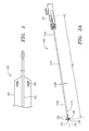
- FIG. 1 provides a general illustration of an apparatus for closing openings formed in blood vessel walls in accordance with the present invention.
- FIG. 2A illustrates one embodiment of a locator assembly for the apparatus of FIG. 1 .
- FIG. 2B illustrates one embodiment of a distal end region of the locator assembly of
- FIG. 2A when the distal end region is in an unexpanded state.
- FIG. 2C illustrates the distal end region of the locator assembly of FIG. 2B when the distal end region is in an expanded state.
- FIG. 2D illustrates one embodiment of a proximal end region of the locator assembly of FIG. 2A .
- FIG. 3A illustrates one embodiment of a carrier assembly for the apparatus of FIG. 1 .
- FIG. 3B illustrates one embodiment of a carrier member for the carrier assembly of FIG. 3A .
- FIG. 3C illustrates one embodiment of a pusher member for the carrier assembly of FIG. 3A .
- FIG. 3D illustrates one embodiment of a cover member for the carrier assembly of FIG. 3A .
- FIG. 3E illustrates one embodiment of a support member for the carrier assembly of FIG. 3A .
- FIG. 4A illustrates a cross-sectional side view of one embodiment of a triggering system for the carrier assembly of FIG. 3A .
- FIG. 4B illustrates a first detailed cross-sectional side view of the triggering system of FIG. 4A .
- FIG. 4C illustrates a detailed view of the triggering system of FIG. 4B .
- FIG. 4D illustrates a second detailed cross-sectional side view of the triggering system of FIG. 4A .
- FIG. 5A illustrates the carrier control system of FIGS. 4A-D as the carrier assembly of FIG. 3A moves distally from an initial predetermined position.
- FIG. 5B illustrates the carrier control system of FIGS. 4A-D as the carrier assembly of FIG. 3A reaches a first predetermined position.
- FIG. 5C illustrates the carrier control system of FIGS. 4A-D as the carrier assembly of FIG. 3A reaches a second predetermined position.
- FIG. 6A illustrates a top view of one embodiment of a closure element in a natural, planar configuration and with a natural cross-section for use with the apparatus of FIG. 1 .
- FIG. 6B illustrates a side view of the closure element of FIG. 6A .
- FIG. 6C illustrates a top view of the closure element of FIGS. 6A-B after a natural cross-section of the closure element has been reduced.
- FIG. 6D illustrates a side view of the reduced closure element of FIG. 6C .
- FIG. 6E illustrates a side view of the reduced closure element of FIGS. 6C-D as the reduced closure element transitions from the natural, planar configuration to a tubular configuration.
- FIG. 6F illustrates a top view of the closure element of FIGS. 6C-D upon completing the transition from the natural, planar configuration to a substantially tubular configuration.
- FIG. 6G illustrates a side view of the closure element of FIG. 6F .
- FIG. 7A illustrates the closure element of FIGS. 6A-G prior to being disposed upon the carrier member of FIG. 3B .
- FIG. 7B illustrates the closure element of FIGS. 6A-G upon being disposed upon the carrier member of FIG. 3B .
- FIG. 7C illustrates the closure element of FIGS. 6A-G as the cover member of FIG. 3D receives the carrier member of FIG. 3B .
- FIG. 7D illustrates the closure element of FIGS. 6A-G being retained substantially within the carrier assembly of FIG. 3A when the carrier member of FIG. 3B is disposed substantially within the cover member of FIG. 3D .
- FIG. 8A illustrates a sheath that is positioned through tissue and into an opening formed in a wall of a blood vessel.
- FIG. 8B illustrates the apparatus of FIG. 1 as prepared to be received by the sheath of FIG. 8A .
- FIG. 8C illustrates a locator assembly of the apparatus of FIG. 8B being advanced distally into the blood vessel.
- FIG. 8D illustrates a distal end region of the locator assembly of FIG. 8C extending into the blood vessel and being transitioned into an expanded state.
- FIG. 8E illustrates the distal end region of FIG. 8D being retracted proximally to engage an inner surface of the blood vessel wall.
- FIG. 8F illustrates a carrier assembly of the apparatus of FIG. 8B being advanced distally into the sheath of FIG. 8A once the distal end region of FIG. 8D has engaged the inner surface of the blood vessel wall.
- FIG. 8G illustrates relative positions of a tube set of the carrier assembly of FIG. 8F upon reaching a first predetermined position.
- FIG. 8H illustrates the relative positions of the tube set of FIG. 8G upon reaching a second predetermined position.
- FIG. 8I illustrates a position of a pusher member of the tube set of FIG. 8H moving distally from the second predetermined position and beginning to distally deploy a closure element.
- FIG. 8J illustrates the closure element of FIG. 8I upon being deployed and engaging tissue adjacent to the opening in the blood vessel wall.
- FIG. 8K illustrates the closure element of FIG. 8J transitioning from the substantially tubular configuration to the natural, planar configuration while engaging the engaged tissue.
- FIG. 8L illustrates the closure element of FIG. 8K drawing the engaged tissue substantially closed and/or sealed
- FIG. 9 illustrates one embodiment of an introducer sheath for the apparatus of FIG. 1 .
- FIG. 10A illustrates an assembly view of the components included in an alternative embodiment of the apparatus for closing openings formed in blood vessel walls.
- FIG. 10B illustrates an assembly view of the components shown in FIG. 10A , showing the reverse view of that shown in FIG. 10A .
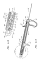
- FIG. 11A illustrates the assembled carrier assembly and triggering assembly of the alternative embodiment of the apparatus shown in FIG. 10A .
- FIG. 11B illustrates a close-up view of the proximal end of the apparatus shown in FIG. 11A .
- FIG. 12 illustrates the apparatus of FIG. 11A after advancement of the locator assembly block.
- FIG. 13A illustrates the apparatus of FIG. 12 after distal advancement of the triggering system and carrier assembly.
- FIG. 13B illustrates a close-up view of the distal end of the housing and internal components of the apparatus shown in FIG. 13A .
- FIG. 14A illustrates the apparatus of FIG. 13 after further distal advancement of the triggering system and carrier assembly.
- FIG. 14B illustrates a close-up view of the distal end of the housing and internal components of the apparatus shown in FIG. 14A .
- FIG. 15 illustrates a reverse view of the apparatus of FIGS. 11-14 , showing the locator release system.
- an apparatus that is configured to prevent inadvertent tissue contact during positioning and to engage a substantial of amount of tissue adjacent to the opening can prove much more desirable and provide a basis for a wide range of medical applications, such as diagnostic and/or therapeutic procedures involving blood vessels or other body lumens of any size. This result can be achieved, according to one embodiment of the present invention, by employing an apparatus 100 as shown in FIG. 1 .
- the apparatus 100 can deliver a closure element 500 (shown in FIGS. 6A-B ) through tissue 630 (shown in FIG. 8A ) and into an opening 610 (shown in FIG. 8A ) formed in and/or adjacent to a wall 620 (shown in FIG. 8A ) of a blood vessel 600 (shown in FIG. 8A ) or other body lumen.
- the closure element (or clip) 500 preferably has a generally annular-shape body 510 (shown in FIGS. 6A-B ) defining a channel 540 and one or more barbs and/or tines 520 (shown in FIGS.
- the closure element 500 has a natural shape and size, the closure element 500 can be deformed into other shapes and sizes, as desired, and is configured to return to the natural shape and size when released.
- the closure element 500 can have a natural, planar configuration with opposing tines 520 and a natural cross-section 530 as shown in FIGS. 6A-B .
- the natural cross-section 530 of the closure element 500 can be reduced to form a reduced closure element 500 ′ that has a natural, planar configuration with opposing tines 520 and a reduced cross-section 530 ′ as shown in FIGS. 6C-D .
- the reduced closure element 500 ′ can be further deformed to form a substantially tubular closure element 500 ′′ (shown in FIG. 6F ) having the reduced cross-section 530 ′ as well as being in a substantially tubular configuration with the tines 520 in an axial configuration.
- the closure element 500 can be formed from any suitable material, including any biodegradable material, any shape memory alloy, such as alloys of nickel-titanium, or any combination thereof.
- the closure element 500 can include radiopaque markers (not shown) or may be wholly or partially formed from a radiopaque material to facilitate observation of the closure element 500 using fluoroscopy or other imaging systems. Exemplary embodiments of a closure element are disclosed in U.S. Pat. No. 6,197,042, in co-pending application Ser. Nos. 09/546,998, 09/610,238, and 10/081,726. The disclosures of these references and any others cited therein are expressly incorporated herein by reference.
- the apparatus 100 is configured to receive and retain the closure element 500 such that the closure element 500 is disposed substantially within the apparatus 100 .
- the closure element 500 can be disposed within, and delivered by way of, a lumen 644 (shown in FIG. 8A ) of the introducer sheath 640 .
- the apparatus 100 also is configured to engage the blood vessel wall 620 adjacent to the opening 610 . Being disposed substantially within the apparatus 100 , the closure element 500 can deeply penetrate, without inadvertently contacting, tissue 630 adjacent to the opening 610 such that the apparatus 100 can position the closure element 500 substantially adjacent to an outer surface 620 a (shown in FIG. 8A ) of the blood vessel wall 620 adjacent to the opening 610 .
- the apparatus 100 can be activated to distally deploy the closure element 500 .
- the apparatus 100 can deploy the closure element 500 without expanding the closure element 500 .
- the closure element 500 when deployed, is configured to engage significant amount of the blood vessel wall 620 and/or tissue 630 adjacent to the opening 610 . Engaging the blood vessel wall 620 and/or tissue 630 , the closure element 500 is further configured to return to the natural cross-section 530 .
- the engaged blood vessel wall 620 and/or tissue 630 are drawn substantially closed and/or sealed, such that, for example, hemostasis within the opening 610 is enhanced.
- the apparatus 100 can be provided as via one or more integrated components and/or discrete components.
- the apparatus 100 can comprise a locator (or obturator) assembly 200 and a carrier assembly 300 .
- the locator assembly 200 and the carrier assembly 300 are shown in FIG. 1 as comprising substantially separate assemblies.
- the locator assembly 200 and the carrier assembly 300 each can be provided, in whole or in part, as one or more integrated assemblies.
- the locator assembly 200 can selectably engage the inner surface 620 b of the blood vessel wall 620 adjacent to the opening 610 . Thereby, the locator assembly 200 is configured to draw the blood vessel wall 620 taut and can maintain the proper position of the apparatus 100 as the blood vessel 600 pulsates.
- the locator assembly 200 can be provided in the manner disclosed in co-pending application Ser. Nos. 09/732,835 and 10/081,723, the disclosure of which is expressly incorporated herein by reference, and preferably includes a flexible or semi-rigid tubular body 210 , such as an elongate rail, with a longitudinal axis 216 . As illustrated in FIG.
- the tubular body 210 has a proximal end region 210 a and a distal end region 210 b and includes a predetermined length 218 a and a predetermined outer cross-section 218 b , both of which can be of any suitable dimension.
- the distal end region 210 b of the locator assembly 200 preferably includes a substantially rounded, soft, and/or flexible distal end or tip 220 to facilitate atraumatic advancement and/or retraction of the distal end region 210 b into the blood vessel 600 .
- a pigtail (not shown) may be provided on the distal end 220 to further aid atraumatic advancement of the distal end region 210 b.
- the distal end region 210 b of the locator assembly 200 further is selectably controllable between an unexpanded state and an expanded state.
- the distal end region 210 b In the unexpanded state, the distal end region 210 b has an unexpanded size; whereas, the distal end region 210 b in the expanded state has an expanded size, which is greater than the unexpanded size of the distal end region 210 b in the unexpanded state.
- the distal end region 210 b is configured to expand from the unexpanded size to the expanded size and/or to contract from the expanded size to the unexpanded size, and the expansion and contraction of the distal end region 210 b preferably is substantially uniform about the longitudinal axis 216 .
- one or more expansion elements 230 can be provided on the distal end region 210 b and can be configured to expand substantially transversely with respect to a longitudinal axis 216 of the locator assembly 200 .
- the expansion elements 230 may include radiopaque markers (not shown) or may be wholly or partially formed from a radiopaque material to facilitate observation of the expansion elements 230 and/or the distal end region 210 b using fluoroscopy or other imaging systems.
- At least one, and preferably all, of the expansion elements 230 can comprise a substantially flexible member 230 ′ with a substantially fixed end region 230 a ′, an intermediate region 230 b ′, and a movable end region 230 c ′ as shown in FIGS. 2B-C .
- the fixed end region 230 a ′ is fixedly coupled with the distal end region 210 b
- the movable end region 230 c ′ is movably coupled with the distal end region 210 b and configured to be axially movable relative to the fixed end region 230 a ′.
- each movable end region 230 c ′ When each movable end region 230 c ′ is axially moved toward the relevant fixed end region 230 a ′, the intermediate regions 230 b ′ buckle and/or expand transversely outwardly, thereby transitioning the distal end region 210 b of the locator assembly 200 from the unexpanded state to the expanded state. In contrast, the distal end region 210 b transitions from the expanded state to the unexpanded state as each of the movable end regions 230 c ′ are axially moved away from the relevant fixed end region 230 a ′.
- the expansion elements 230 are shown as comprising the flexible members 230 ′ in FIGS. 2B-C for purposes of illustration, it is understood that the expansion elements 230 can comprise any type of expansion elements and are not limited to the illustrated embodiments.
- the locator assembly 200 also can include a locator control system 240 that is coupled with the proximal end region 210 a of the locator assembly 200 and that is configured to selectively control the distal end region 210 b of the locator assembly 200 between the unexpanded and expanded states.
- the locator control system 240 can selectively control the distal end region 210 b between the unexpanded and expanded states, such as by being activated by a switching system (not shown).
- a control member 250 such as a rod, wire, or other elongate member, can be moveably disposed within a lumen (not shown) formed by the tubular body 210 and extending substantially between the proximal end region 210 a and the distal end region 210 b .
- the control member 250 has a proximal end region 250 a that is coupled with the locator control system 240 , preferably via a control block 260 (shown in FIG. 4D ), and a distal end region (not shown) that is coupled with the distal end region 210 b of the locator assembly 200 , the expansion elements 230 , and/or the movable end regions 230 c ′ of the substantially flexible members 230 ′.
- the locator control system 240 can selectively transition the distal end region 210 b , the expansion elements 230 , and/or the substantially flexible members 230 ′ between the unexpanded and expanded states by moving the control member 250 axially relative to the tubular body 210 .
- the locator control system 240 preferably includes a locator release system 490 for maintaining the unexpanded state and/or the expanded state of the distal end region 210 b , the expansion elements 230 , and/or the substantially flexible members 230 ′.
- the locator release system 490 can comprise any type of locking system and can be engaged, for instance, by activating the switching system.
- the locator release system 490 can secure the control member 250 to prevent axial movement relative to the tubular body 210 , thereby maintaining the substantially flexible members 230 ′ in the expanded state.
- the locator control system 240 also can be configured to disengage the locator release system 490 , such that the distal end region 210 b , the expansion elements 230 , and/or the substantially flexible members 230 ′ can transition between the unexpanded and expanded states.
- the locator release system 490 can be disengaged, for example, by activating an emergency release system (not shown).
- the locator control system 240 can further include a biasing system (not shown), such as one or more springs, to bias the distal end region 210 b , the expansion elements 230 , and/or the substantially flexible members 230 ′ to enter and/or maintain the unexpanded state when the locator release system 490 is disengaged.
- the carrier assembly 300 is coupled with, and slidable relative to, the locator assembly 200 .
- the carrier assembly 300 is configured to receive and retain the closure element 500 (shown in FIGS. 6A-B ), which preferably is disposed substantially within the carrier assembly 300 .
- the locator assembly 200 engages the inner surface 620 b (shown in FIG. 8A ) of the blood vessel wall 620 (shown in FIG. 8A )
- the carrier assembly 300 is further configured to position the closure element 500 substantially adjacent to the opening 610 (shown in FIG. 8A ) and to deploy the closure element 500 .
- the closure element 500 can maintain the reduced cross-section 530 ′ (shown in FIGS.
- the closure element 500 when deployed, can engage significant amount of the blood vessel wall 620 and/or tissue 630 adjacent to the opening 610 . Thereafter, the closure element 500 is configured to return to the natural cross-section 530 , preferably substantially uniformly, such that the blood vessel wall 620 and/or tissue 630 is drawn substantially closed and/or sealed.
- the carrier assembly 300 can include a tube set 305 , comprising a carrier member 310 , a pusher member 320 , and a cover member 330 .
- the carrier member 310 , the pusher member 320 , and the cover member 330 can be provided as a plurality of nested, telescoping members with a common longitudinal axis 350 as illustrated in FIG. 3A .
- the carrier member 310 is configured to receive and support the closure element 500 . While being disposed on the carrier member 310 , the closure element 500 preferably is deformed from the natural, planar configuration to form the substantially tubular closure element 500 ′′ (shown in FIGS. 6F-G ) as will be discussed in more detail below. Being disposed substantially about, and supported by, an outer periphery 312 b of the carrier member 310 , the substantially tubular closure element 500 ′′ can be substantially in axial alignment with the carrier member 310 with the tines 520 pointed substantially distally.
- the carrier member 310 has a proximal end region 310 a and a distal end region 310 b and includes a predetermined length 318 a and a predetermined cross-section 318 b , both of which can be of any suitable dimension.
- the carrier member 310 also can define a lumen 314 that extends substantially between the proximal end region 310 a and the distal end region 310 b and that is configured to slidably receive at least a portion of the tubular body 210 of the locator assembly 200 .
- the distal end region 310 b of the carrier member 310 preferably has a cross-section that increases distally, as illustrated in FIGS. 3A-B , for substantially uniformly expanding the substantially tubular closure element 500 ′′ beyond the natural cross-section 530 of the closure element 500 when the substantially tubular closure element 500 ′′ is deployed.
- the distal end region 310 b can be formed with a cross-section (not shown) that is substantially uniform.
- the distal end region 310 b of the carrier member 310 can be provided with the substantially-uniform cross-section and that the substantially tubular closure element 500 ′′ can be deployed without being expanded.
- the pusher member 320 Being configured to distally deploy the substantially tubular closure element 500 ′′, the pusher member 320 has a proximal end region 320 a and a distal end region 320 b and is coupled with, and slidable relative to, the carrier member 310 .
- the pusher member 320 includes a predetermined length 328 a and a predetermined cross-section 328 b , both of which can be of any suitable dimension and can be configured to slidably receive the carrier member 310 such that the distal end region 320 b of the pusher member 320 is offset proximally from the distal end region 310 b of the carrier member 310 .
- the predetermined length 328 a of the pusher member 320 can be greater than or substantially equal to the predetermined length 318 a of the carrier member 310 .
- the predetermined length 328 a of the pusher member 320 however preferably is less than the predetermined length 318 a of the carrier member 310 such that the carrier member 310 and the pusher member 320 at least partially define a space 360 distal to the distal end region 320 b of the pusher member 320 and along the periphery 312 b of the carrier member 310 .
- the pusher member 320 preferably is substantially tubular and can define a lumen 324 that extends substantially between the proximal end region 320 a and the distal end region 320 b and that is configured to slidably receive at least a portion of the carrier member 310 .
- the cross-section 328 b of the pusher member 320 preferably is substantially uniform, and the distal end region 320 b of the pusher member 320 can comprise one or more longitudinal extensions 325 , which extend distally from the pusher member 320 and along the periphery 312 b of the carrier member 310 as shown in FIG. 3C .
- the longitudinal extensions 325 preferably are biased such that the longitudinal extensions 325 extend generally in parallel with common longitudinal axis 350 .
- the longitudinal extensions 325 are sufficiently flexible to expand radially, and yet sufficiently rigid to inhibit buckling, as the distal end region 320 b is directed distally along the carrier member 310 and engage the distally-increasing cross-section of the distal end region 310 b of the carrier member 310 to deploy the substantially tubular closure element 500 ′′.
- the cover member 330 is configured to retain the substantially tubular closure element 500 ′′ substantially within the carrier assembly 300 prior to deployment. Being coupled with, and slidable relative to, the pusher member 320 , the cover member 330 has a proximal end region 330 a and a distal end region 330 b and includes a predetermined length 338 a and a predetermined cross-section 338 b , both of which can be of any suitable dimension.
- the cover member 330 Preferably being formed as a substantially rigid, semi-rigid, or flexible tubular member, the cover member 330 has an inner periphery 332 a and an outer periphery 332 b and can define a lumen 334 .
- the lumen 334 extends substantially between the proximal and distal end regions 330 a , 330 b of the cover member 330 and can be configured to slidably receive at least a portion of the pusher member 320 .
- the distal end region 330 b is configured to extend over the space 360 , thereby defining an annular cavity 370 for receiving and retaining the substantially tubular closure element 500 ′′.
- the cross-section 338 b of the cover member 330 preferably is substantially uniform, and the distal end region 330 b of the cover member 330 preferably comprises one or more longitudinal extensions 335 , which extend distally from the cover member 330 and along an outer periphery 322 b of the pusher member 320 as shown in FIG. 3D .
- the longitudinal extensions 335 can extend generally in parallel with common longitudinal axis 350
- the longitudinal extensions 335 preferably are biased such that the plurality of longitudinal extensions 335 extend substantially radially inwardly as illustrated in FIGS. 3A and 3D .
- the longitudinal extensions 335 can at least partially close the lumen 334 substantially adjacent to the distal end region 330 b of the cover member 330 .
- the longitudinal extensions 335 preferably are sufficiently flexible to expand radially to permit the distal end region 310 b of the carrier member 310 to move distally past the cover member 330 to open the annular cavity 370 such that the distal end region 330 b no longer extends over the space 360 .
- the carrier member 310 is at least partially disposed within, and slidable relative to, the lumen 324 of the pusher member 320 .
- the pusher member 320 is at least partially disposed within, and slidable relative to, the lumen 334 of the cover member 330 .
- the tubular body 210 of the locator assembly 200 is at least partially disposed within, and slidable relative to, the lumen 314 of the carrier member 310 .
- the longitudinal axis 216 of the locator assembly 200 preferably is substantially in axial alignment with the common longitudinal axis 350 of the carrier member 310 , the pusher member 320 , and the cover member 330 .
- the tube set 305 preferably also includes a support member 340 as shown in FIGS. 3A and 3E .
- the support member 340 is configured to slidably receive the tubular body 210 of the locator assembly 200 and to provide radial support for the distal end region 210 b of the tubular body 210 when the locator assembly 200 is coupled with the carrier assembly 300 .
- the carrier assembly 300 can advantageously include the support member 340 , for example, if the tubular body 210 is not sufficiently rigid or under other circumstances in which support for the tubular body 210 might be desirable.
- the support member 340 also can be configured to inhibit the plurality of longitudinal extensions 335 , which extend from the distal end region 330 b of the cover member 330 , from expanding prematurely when the closure element 500 is deployed.
- the support member 340 Preferably being formed as a substantially rigid, semi-rigid, or flexible tubular member, the support member 340 includes a proximal end region 340 a and a distal end region 340 b . Having an outer periphery 342 b , the support member 340 can define a lumen 344 that extends substantially between the proximal end region 340 a and the distal end region 340 b and that is configured to slidably receive and support at least a portion of the tubular body 210 of the locator assembly 200 .
- the support member 340 can be at least partially slidably disposed within the lumen 314 of the carrier member 310 such that the tubular body 210 of the locator assembly 200 is coupled with, and slidable relative to, the carrier member 310 in the manner described in more detail above.
- the support member 340 has a predetermined length 348 a and a predetermined cross-section 348 b , both of which can be of any suitable dimension, and the cross-section 348 b preferably is substantially uniform.
- the carrier member 310 , the pusher member 320 , the cover member 330 , and/or the support member 340 can be provided, in whole or in part, as one or more integrated assemblies.
- the carrier assembly 300 also can include a housing 380 as illustrated in FIG. 4A .
- the housing 380 Preferably being formed as an elongate member with a longitudinal axis 386 , the housing 380 has an outer periphery 382 b and includes a proximal end region 380 a and a distal end region 380 b .
- the tubular body 210 of the locator assembly 200 at least partially disposed within, and slidable relative to, the tube set 305 such that the distal end region 210 b of the tubular body 210 extends beyond the distal end regions 310 b , 320 b , 330 b , and/or 340 b .
- the tubular body 210 , the carrier member 310 , the pusher member 320 , the cover member 330 , and, if provided, the support member 340 are at least partially disposed within, and slidable relative to, the housing 380 , and the respective distal end regions 210 b , 310 b , 320 b , 330 b , and 340 b extend from the distal end region 380 b of the housing 380 such that the common longitudinal axis 350 (shown in FIG. 3A ) of the tube set 305 is substantially axially aligned with the longitudinal axis 386 of the housing 380 .
- the housing 380 supports the tube set 305 and can have one or more handles 390 to facilitate use of the apparatus 100 .
- the handles 390 extend substantially radially from the outer periphery 382 b of the housing 380 and can be provided in the manner known in the art.
- the tubular body 210 of the locator assembly 200 is at least partially disposed within, and slidable relative to, the tube set 305 of the carrier assembly 300 such that the distal end region 210 b of the tubular body 210 extends beyond the distal end regions 310 b , 320 b , 330 b , and/or 340 b .
- the proximal end region 210 a of the tubular body 210 and the proximal end regions 310 a , 320 a , 330 a , and/or 340 a of the tube set 305 are at least partially disposed within, and slidable relative to, the housing 380 .
- the switching system of the locator assembly 200 and a switching system 450 of the triggering system 400 preferably are accessible external to the housing 380 as shown in FIG. 4A .
- a triggering system 400 can be disposed substantially within the housing 380 .
- the triggering system 400 is configured to control the relative axial movement and/or positioning of the respective distal end regions 310 b , 320 b , 330 b , and 340 b of the tube set 305 and/or the distal end region 210 b of the locator assembly 200 .
- the triggering system 400 can control the relative axial movement of the distal end regions 210 b , 310 b , 320 b , 330 b , and/or 340 b in any manner, such as by being activated by the switching system 450 .
- the triggering system 400 can induce axial motion, such as distal motion, with respect to one or more of the distal end regions 210 b , 310 b , 320 b , 330 b , and/or 340 b .
- One or more of the distal end regions 210 b , 310 b , 320 b , 330 b , and/or 340 b can be axially moved.
- Axial motion of one or more of the carrier member 310 , the pusher member 320 , the cover member 330 , and the support member 340 and/or the tubular body 210 can be attained, for example, by applying an axial force to the switching system 450 .
- one or more of the distal end regions 210 b , 310 b , 320 b , 330 b , and/or 340 b may include radiopaque markers (not shown) or may be wholly or partially formed from a radiopaque material.
- the triggering system 400 is configured to overcome internal resistance such that the relative axial movement and/or positioning of the respective distal end regions 310 b , 320 b , 330 b , and 340 b of the tube set 305 and/or the distal end region 210 b of the locator assembly 200 are controlled in accordance with a predetermined manner when the triggering system 400 is activated. Thereby, movement and/or positioning of the distal end regions 310 b , 320 b , 330 b , 340 b , and/or 210 b is initiated when at least a predetermined quantity of force is applied to the switching system 450 .
- a force that is less than the predetermined quantity generally is insufficient to activate the triggering system 400 ; whereas, when the force increases to a level that is greater than or substantially equal to the predetermined quantity, the triggering system 400 is configured to activate, moving and/or positioning the distal end regions 310 b , 320 b , 330 b , 340 b , and/or 210 b in accordance with the predetermined manner.
- the triggering system 400 once activated, preferably continues to move and/or position the distal end regions 310 b , 320 b , 330 b , 340 b , and/or 210 b in accordance with the predetermined manner until the closure element 500 is deployed.
- the triggering system 400 can comprise one or more sets of cooperating detents for coupling the axial motion of the distal end regions 310 b , 320 b , 330 b , and 340 b in accordance with a predetermined manner when the triggering system 400 is activated.
- detents refers to any combination of mating elements, such as blocks, tabs, pockets, slots, ramps, locking pins, cantilevered members, support pins, and the like, that may be selectively or automatically engaged and/or disengaged to couple or decouple the carrier member 310 , the pusher member 320 , the cover member 330 , and the support member 340 relative to one another.
- the cooperating detents as illustrated and described below are merely exemplary and not exhaustive.
- the cooperating detents can include a first set of cooperating blocks and pockets for releasable coupling the support member 340 , the carrier member 310 , the pusher member 320 , and the cover member 330 .
- the support member 340 can be decoupled from the carrier member 310 , the pusher member 320 , and the cover member 330 and preferably is substantially inhibited from further axial movement.
- the carrier member 310 , the pusher member 320 , and the cover member 330 may continue to be directed distally as the support member 340 remains substantially stationary.
- the cooperating detents can comprise a carrier block 410 , a pusher block 420 , a cover block 430 , and a support block 440 , which can be configured to couple and decouple in accordance with the predetermined manner.
- the carrier block 410 is disposed on the proximal end region 310 a of the carrier member 310 and includes a carrier pin 412 c that extends from the carrier block 410 ; whereas, the proximal end region 330 a of the cover member 330 and the proximal end region 340 a the support member 340 are respectively coupled with the cover block 430 and the support block 440 .
- a cover pin 432 b extends from the cover block 430
- the support block 440 has a support pin 442 a , which extends from the support block 440 .
- the support pin 442 a , the cover pin 432 b , and the carrier pin 412 c each preferably are formed from a substantially rigid material, such as an alloy of nickel-titanium.
- the pusher block 420 is disposed on the proximal end region 320 a of the pusher member 320 and forms a support slot 422 a , a cover slot 422 b , and a carrier slot 422 c .
- the support slot 422 a is configured to receive and releasable engage the support pin 442 a by which the support member 340 can be coupled with, and decoupled from, the pusher member 320 .
- the cover member 330 can be coupled with, and decoupled from, the pusher member 320 via the cover slot 422 b , which is configured to receive and releasable engage the cover pin 432 b .
- the carrier slot 422 c is configured to receive and releasable engage the carrier pin 412 c such that the carrier member 310 can be coupled with, and decoupled from, the pusher member 320 .
- the carrier block 410 , the pusher block 420 , the cover block 430 , and the support block 440 preferably are respectively disposed substantially on the outer peripheries 312 b , 322 b , 332 b , and 342 b and can be configured to couple and decouple in accordance with the predetermined manner.
- the triggering system 400 also includes one or more stops for engaging the pusher block 420 , the cover block 430 , and/or the support block 440 , respectively.
- a support stop 460 a , a cover stop 460 b , and a carrier stop 460 c each are formed in the housing 380 and are configured to receive, and substantially inhibit further movement of, the support block 440 , the cover block 430 , and the carrier block 410 , respectively, in accordance with the predetermined manner.
- the cover block 430 moves distally within the housing 380 , and the cover block 430 approaches the cover stop 460 b .
- the cover block 430 Upon being received by the cover stop 460 b , the cover block 430 is substantially locked in place, substantially preventing any further motion by the cover block 430 .
- the cover pin 412 b Resisting the axial force, the cover pin 412 b provides a static load while the axial force is less than the predetermined quantity of force. As the axial force increases to a level that is greater than or substantially equal to the predetermined quantity, the cover pin 412 b can be displaced from the cover slot 422 b , decoupling the cover member 330 from the carrier member 310 , the pusher member 320 , and the support member 340 .
- the static forces provided by the pins 412 a , 412 b , and 412 c is approximately proportional to a composition and cross-section of the respective pins 412 a , 412 b , and 412 c and/or a depth and a slope of the respective slots 422 a , 422 b , and 422 c .
- the pins 412 a , 412 b , and 412 c can be configured to provide static loads that are differing and/or substantially uniform.
- the triggering system 400 can further have a tube release system 470 for inhibiting inadvertent advancement of the tube set 305 .
- the tube release system 470 is coupled with a tube release member 480 , such as a rod, wire, or other elongate member.
- the tube release member 480 has a proximal end region 480 a that is disposed substantially between the pusher block 420 and the housing 380 (shown in FIG. 4A ) and a distal end region 480 b that is coupled with the tube release system 470 .
- a tab 485 is coupled with the proximal end region 480 a of the tube release member 480 , and a pin (not shown) extends from the pusher block 420 and is disposed substantially between the tab 485 and a groove (not shown) formed in the housing 380 .
- the tube release system 470 is configured to release the tube set 305 when the tube release member 480 is moved proximally, freeing the pusher block 420 .
- a locator release system 490 for permitting the distal end region 210 b , the expansion elements 230 , and/or the substantially flexible members 230 ′ of the locator assembly 200 to transition from the expanded state to the unexpanded state can be included with the triggering system 400 .
- the locator release system 490 can comprise a rod, wire, or other elongate member and has a proximal end region 490 a and a distal end region 490 b .
- the proximal end region 490 a of the locator release system 490 can be coupled with, and configured to activate, the locator control system 240 (shown in FIG. 2D ), and the distal end region 490 b extends beyond the pusher block 420 .
- the control block 260 is disengaged such that the distal end region 210 b , the expansion elements 230 , and/or the substantially flexible members 230 ′ of the locator assembly 200 to transition from the expanded state to the unexpanded state.
- FIGS. 5A-C The operation of the triggering system 400 in accordance with one predetermined manner is illustrated in FIGS. 5A-C with the closure element 500 (shown in FIGS. 6A-B ) disposed substantially within the apparatus 100 .
- the distal end region 210 b of the locator assembly 200 has been positioned as desired and has transitioned from the unexpanded state to the expanded state.
- the locator control system 240 shown in FIG. 2D
- a distally-directed axial force is applied to the triggering system 400 via the switching system 450 .
- the tube release member 480 shown in FIG.
- the tube set 305 is substantially freely slidable within the housing 380 and responds to the axial force by sliding distally from an initial predetermined position to a first predetermined position.
- the carrier member 310 , the pusher member 320 , the cover member 330 , and the support member 340 are coupled via the slots 422 c , 422 b , and 422 a (shown in FIG. 4C ) and the pins 412 c , 422 b , and 442 a (shown in FIG. 4C ).
- the support pin 442 a , the cover pin 432 b , and the carrier pin 412 c are respectively disposed within, and engaged by, the support slot 422 a , the cover slot 422 b , and the carrier slot 422 c such that the carrier block 410 , the pusher block 420 , the cover block 430 , and the support block 440 are coupled as illustrated in FIG. 4C . Therefore, the carrier member 310 , the pusher member 320 , the cover member 330 , and the support member 340 each slide distally from the initial predetermined position to the first predetermined position in response to the axial force.
- FIG. 5B illustrates the positions of the carrier member 310 , the pusher member 320 , the cover member 330 , and the support member 340 upon reaching the first predetermined position.
- the support block 440 and the cover block 430 respectively engage the support stop 460 a and the cover stop 460 b .
- the support stop 460 a receives, and substantially inhibits further movement of, the support block 440 and, therefore, the support member 340 ;
- the cover stop 460 b receives, and substantially inhibits further movement of, the cover block 430 and, therefore, the cover member 330 .
- the support block 440 and the cover block 430 preferably engage the support stop 460 a and the cover stop 460 b in the first predetermined position
- the support block 440 can engage the support stop 460 a and the cover block 430 can engage the cover stop 460 b in different predetermined positions.
- the predetermined manner can comprise any number of predetermined positions, each predetermined position being associated with any number of the blocks 410 , 420 , 430 , and 440 engaging any number of relevant stops 460 a , 460 b , and 460 c.
- the carrier member 310 and the pusher member 320 can be decoupled from the cover member 330 and the support member 340 by disengaging the support pin 442 a and the cover pin 432 b from the support slot 422 a and the cover slot 422 b , respectively.
- the support pin 442 a and the cover pin 432 b each resist the axial force. While the axial force is less than the combined static force provided by the support pin 442 a and the cover pin 432 b , the carrier member 310 and the pusher member 320 remain coupled with the cover member 330 and the support member 340 .
- the support pin 442 a and the cover pin 432 b are respectively displaced from the support slot 422 a and the cover slot 422 b , decoupling the carrier member 310 and the pusher member 320 from the cover member 330 and the support member 340 .
- the cover member 330 and the support member 340 preferably are inhibited from further distal movement and remain substantially stationary; whereas, the carrier member 310 and the pusher member 320 proceed distally toward a second predetermined position.
- the pusher member 320 and the carrier member 310 continue distally until the second predetermined position is reached as shown in FIG. 5C .
- the carrier block 410 engages the carrier stop 460 c .
- the carrier stop 460 c receives, and substantially inhibits further movement of, the carrier block 410 and, therefore, the carrier member 310 .
- the pusher member 320 can be decoupled from the carrier member 310 by disengaging the carrier pin 412 c from the carrier slot 422 c .
- the carrier pin 412 c resists the axial force. While the axial force is less than the static force provided by the carrier pin 412 c , the pusher member 320 remains coupled with the carrier member 310 .
- the carrier pin 412 c is displaced from the carrier slot 422 c , decoupling the pusher member 320 from the carrier member 310 .
- the carrier member 310 preferably is inhibited from further distal movement and remains substantially stationary; whereas, the pusher member 320 proceed distally to deploy the closure element 500 and to activate the locator release system 490 (shown in FIG. 2D ) such that the distal end region 210 b , the expansion elements 230 , and/or the substantially flexible members 230 ′ of the locator assembly 200 transition from the expanded state to the unexpanded state.
- the axial force that is applied to overcome the static force associated with the first predetermined position is sufficient to overcome the static forces associated with the subsequent predetermined positions, to deploy the closure element 500 , and to activate the locator release system 490 such that the triggering system 400 operates in one substantially-continuous motion.
- the triggering system 400 can include an energy storing element (not shown), which can be disposed substantially between the housing 380 and the blocks 410 , 420 , 430 , and 440 and which is configured to store potential energy for moving the tube set 305 from the initial predetermined position through the other predetermined positions, deploying the closure element 500 , and/or activating the locator release system 490 .
- the energy storing element is configured store the potential energy when the tube set 305 is in the initial predetermined position and to release the potential energy, when activated, such that the tube set 305 travels through the predetermined positions at a substantially constant and continuous rate.
- the energy storing element can comprise one or more springs (not shown). Each of the springs can be in a compressed state when the tube set 305 is in the initial predetermined position and released from the compressed state when the switching system 450 of the triggering system 400 is activated.
- the closure element 500 is disposed within the carrier assembly 300 .
- the reduced closure element 500 ′ can be slidably received over the distally-increasing cross-section 318 b of the distal end region 310 b of the carrier member 310 and disposed about the periphery 312 of the carrier member 310 adjacent to the space 360 . Since the reduced cross-section 530 ′ of the reduced closure element 500 ′ is less than the cross-section 318 b of the distally-increasing cross-section 318 b , the reduced closure element 500 ′ must be temporarily radially deformed to be received over the distal end region 310 b .
- the reduced closure element 500 ′ As the reduced closure element 500 ′ is received over the distal end region 310 b , the opposing tines 520 of the reduced closure element 500 ′ engage the distal end region 310 b .
- the reduced closure element 500 ′ thereby forms the substantially tubular closure element 500 ′′ in the manner described in more detail above with reference to FIGS. 6E-G .
- the substantially tubular closure element 500 ′′ is disposed about the space 360 , and the tines 520 are directed substantially distally as shown in FIG. 7B .
- one or more of the tines 520 can be disposed proximally of the distally-increasing cross-section 318 b of the distal end region 310 b , as illustrated in FIG. 7B , and/or can be at least partially disposed upon, and contact, the distally-increasing cross-section 318 b of the distal end region 310 b .
- the substantially tubular closure element 500 ′′ preferably is disposed on the carrier member 310 such that the tines 520 define a first plane that is substantially perpendicular to a second plane defined by the switching system 450 and/or the handles 390 (collectively shown in FIG. 5A ).
- the substantially tubular closure element 500 ′′ can be retained on the outer periphery 312 b of the carrier member 310 when distal end region 310 b of the carrier member 310 and the distal end region 320 b of the pusher member 320 are slidably received within the lumen 334 of the cover member 330 as illustrated in FIGS. 7C-D .
- the distal end region 330 b of the cover member 330 extends over the space 360 and defines the annular cavity 370 for retaining the substantially tubular closure element 500 ′′.
- the substantially tubular closure element 500 ′′ is disposed substantially between the outer periphery 312 b of the carrier member 310 and the inner periphery 332 a of the cover member 330 such that the substantially tubular closure element 500 ′′ maintains the substantially tubular configuration with the tines 520 being directed substantially distally.
- the tube set 305 may radially compress the substantially tubular closure element 500 ′′ such that the substantially tubular closure element 500 ′′ enters and maintains a compressed tubular configuration.
- the body 510 of the substantially tubular closure element 500 ′′ can be disposed distally of the distal end region 320 b of the pusher member 320 , as illustrated in FIGS. 7C-D , or can engage the distal end region 320 b , as desired.
- a sheath 640 may be inserted or otherwise positioned through skin 650 and tissue 630 and within the blood vessel 600 or other body lumen via the opening 610 .
- the sheath 640 has a proximal end region 640 a and a distal end region 640 b and includes a predetermined length and a predetermined cross-section, both of which can be of any suitable dimension.
- the sheath 640 also forms a lumen 644 that extends along a longitudinal axis of the sheath 640 and substantially between the proximal and distal end regions 640 a , 640 b .
- the lumen 644 can have any suitable internal cross-section 648 b and is suitable for receiving one or more devices (not shown), such as a catheter, a guide wire, or the like.
- the lumen 644 is configured to slidably receive the tubular body 210 of the locator assembly 200 (shown in FIG. 4A ) and/or the tube set 305 of the carrier assembly 300 (shown in FIG. 4A ).
- the sheath 640 may be configured to radially expand, such as by stretching, to receive the tube set 305 .
- the sheath 640 can be advantageously configured to split as the tube set 305 is received by, and advances within, the lumen 644 of the sheath 640 , thereby permitting the apparatus 100 to access the blood vessel wall 620 .
- the sheath 640 can include one or more splits 645 , such as longitudinal splits, each split being provided in the manner known in the art.
- Each split 645 is configured to split the sheath 640 in accordance with a predetermined pattern, such as in a spiral pattern. It will be appreciated that, when the internal cross-section 648 b of the sheath 640 is greater than the predetermined cross-section 338 b of the cover member 330 , it may not be necessary for the sheath 640 to be configured to radially expand and/or split.
- the sheath 640 may be advanced over a guide wire or other rail (not shown) that was previously positioned through the opening 610 and into the blood vessel 600 using conventional procedures.
- the blood vessel 600 is a peripheral blood vessel, such as a femoral or carotid artery, although other body lumens may be accessed using the sheath 640 as will be appreciated by those skilled in the art.
- the opening 610 , and consequently the sheath 640 may be oriented with respect to the blood vessel 600 such as to facilitate the introduction of devices through the lumen 644 of the sheath 640 and into the blood vessel 600 with minimal risk of damage to the blood vessel 600 .
- One or more devices may be inserted through the sheath 640 and advanced to a preselected location within the patient's body.
- the devices may be used to perform a therapeutic or diagnostic procedure, such as angioplasty, atherectomy, stent implantation, and the like, within the patent's vasculature.
- the devices are removed from the sheath 640 , and the apparatus 100 is prepared to be received by the lumen 644 of the sheath 640 as shown in FIG. 8B .
- the distal end region 210 b of the tubular body 210 of the locator assembly 200 is slidably received by the lumen 644 and atraumatically advanced distally into the blood vessel 600 as illustrated in FIGS. 8B-C .
- the distal end region 210 b of the tubular body 210 can transition from the unexpanded state to the expanded state as shown in FIG. 8D by activating the switching system of the locator assembly 200 .
- the apparatus 100 and the sheath 640 then are retracted proximally until the distal end region 210 b is substantially adjacent to an inner surface 620 b of the blood vessel wall 620 .
- the distal end region 210 b thereby draws the blood vessel wall 620 taut and maintains the proper position of the apparatus 100 as the blood vessel 600 pulsates. Since the expanded cross-section of the distal end region 210 b is greater than or substantially equal to the cross-section of the opening 610 and/or the cross-section of the lumen 644 , the distal end region 210 b remains in the blood vessel 600 and engages the inner surface 620 b of the blood vessel wall 620 .
- the distal end region 210 b can frictionally engage the inner surface 620 b of the blood vessel wall 620 , thereby securing the apparatus 100 to the blood vessel 600 .
- the sheath 640 is retracted proximally such that the distal end region 640 b of the sheath 640 is substantially withdrawn from the blood vessel 600 , as shown in FIG. E, permitting the apparatus 100 to access the blood vessel wall 620 .
- the apparatus 100 preferably also is axially rotated such that the first plane defined by the tines 520 of the substantially tubular closure element 500 ′′ is substantially parallel with a third plane defined by the blood vessel 600 .
- the engagement between the substantially tubular closure element 500 ′′ and the blood vessel wall 620 and/or tissue 630 can be improved because the tines 520 are configured to engage the blood vessel wall 620 and/or tissue 630 at opposite sides of the opening 610 .
- the substantially tubular closure element 500 ′′ is disposed on the carrier member 310 such that the first plane defined by the tines 520 is substantially perpendicular to the second plane defined by the switching system 450 and/or the handles 390 (collectively shown in FIG. 5A ), for example, the apparatus 100 can be positioned such that the second plane defined by the switching system 450 and/or the handles 390 is substantially perpendicular to the third plane defined by the blood vessel 600 .
- the tube release system 470 (shown in FIG. 4D ) is activated to release the tube set 305 , which can be advanced distally and received within the lumen 644 of the sheath 640 as illustrated in FIG. 8F .
- the sheath 640 can radially expand and/or split in accordance with the predetermined pattern as the tube set 305 advances because the internal cross-section 648 b of the sheath 640 is less than or substantially equal to the predetermined cross-section 338 b of the cover member 330 .
- the carrier member 310 , the pusher member 320 , the cover member 330 , and the support member 340 each advance distally and approach the first predetermined position as illustrated in FIG. 8G .
- the tube set 305 Upon reaching the first predetermined position, the tube set 305 is disposed substantially adjacent to the outer surface 620 a of the blood vessel wall 620 adjacent to the opening 610 such that the blood vessel wall 620 adjacent to the opening 610 is disposed substantially between the expanded distal region 210 b of the locator assembly 200 and the tube set 305 .
- the cover member 330 and the support member 340 each decouple from the carrier member 310 and the pusher member 320 in the manner described in more detail above with reference to FIGS. 5A-C when the tube set 305 is in the first predetermined position. Thereby, the cover member 330 and the support member 340 preferably are inhibited from further axial movement and remain substantially stationary as the carrier member 310 and the pusher member 320 each remain coupled and axially slidable.
- the cover member 330 and the support member 340 remaining substantially stationary while the carrier member 310 and the pusher member 320 continue distally and approach the second predetermined position.
- the annular cavity 370 moves distally relative to the substantially-stationary cover member 330 such that the distal end region 330 b of the cover member 330 no longer encloses the annular cavity 370 .
- the substantially tubular closure element 500 ′′ is not completely enclosed by the annular cavity 370 formed by the distal end regions 310 b , 320 b , and 330 b of the carrier member 310 , the pusher member 320 , and the cover member 330 .
- the substantially tubular closure element 500 ′′ is advantageously retained on the outer periphery 312 b of the carrier member 310 by the distal end region 330 b of the cover member 330 as illustrated in FIG. 8H .
- the apparatus 100 is configured to provide better tissue penetration.
- the carrier member 310 decouples from the pusher member 320 in the manner described in more detail above with reference to FIGS. 5A-C . Therefore, the carrier member 310 , the cover member 330 , and the support member 340 preferably are inhibited from further axial movement and remain substantially stationary; whereas, the pusher member 320 remains axially slidable. As the pusher member 320 continues distally, the distal end region 320 b of the pusher member 320 engages the substantially tubular closure element 500 ′′ and displaces the substantially tubular closure element 500 ′′ from the space 360 as shown in FIG. 8I .
- the pusher member 320 directs the substantially tubular closure element 500 ′′ over the distally-increasing cross-section of the distal end region 310 b of the substantially-stationary carrier member 310 such that the cross-section 530 ′ (shown in FIGS. 6F-G ) of the substantially tubular closure element 500 ′′ begins to radially expand, preferably in a substantially uniform manner.
- the cross-section 530 ′ of the substantially tubular closure element 500 ′′ radially expands beyond natural cross-section 530 (shown in FIGS. 6A-B ) of the closure element 500 .
- the substantially tubular closure element 500 ′′ Upon being directed over the distally-increasing cross-section of the distal end region 310 b by the pusher member 320 , the substantially tubular closure element 500 ′′ is distally deployed as illustrated in FIG. 8J .
- the tines 520 can pierce and otherwise engage significant amount of the blood vessel wall 620 and/or tissue 630 adjacent to the opening 610 .
- the tines 520 can engage significant amount of the blood vessel wall 620 and/or tissue 630 because the cross-section 530 ′ of the substantially tubular closure element 500 ′′ is expanded beyond natural cross-section 530 of the closure element 500 during deployment.
- the distal end region 210 b of the locator assembly 200 also begins to retract proximally and the locator release system 490 (shown in FIG. 4D ) can be activated to transition from the expanded state to the unexpanded state as the substantially tubular closure element 500 ′′ is deployed as shown in FIG. 8J .
- the distal end region 210 b of the locator assembly 200 retracts proximally and transitions from the expanded state to the unexpanded state substantially simultaneously with the deployment of the substantially tubular closure element 500 ′′.
- the distal end region 210 b may be configured to draw the blood vessel wall 620 and/or tissue 630 adjacent to the opening 610 proximally and into the channel 540 defined by the substantially tubular closure element 500 ′′.
- the tines 520 of the substantially tubular closure element 500 ′′ thereby can pierce and otherwise engage the drawn blood vessel wall 620 and/or tissue 630 . Since the cross-section 530 ′ of the substantially tubular closure element 500 ′′ is expanded beyond natural cross-section 530 of the closure element 500 , a significant amount of the blood vessel wall 620 and/or tissue 630 can be drawn into the channel 540 and engaged by the tines 520 .
- the substantially tubular closure element 500 ′′ once deployed, begins to transition from the tubular configuration, returning to the natural, planar configuration with opposing tines 520 and a natural cross-section 530 of the closure element 500 .
- the substantially tubular closure element 500 ′′ substantially uniformly transitions from the tubular configuration to the natural, planar configuration. Rotating axially inwardly to form the opposing tines 520 of the closure element 500 , the tines 520 draw the tissue 630 into the channel 540 as the substantially tubular closure element 500 ′′ forms the closure element 500 .
- tissue 630 is drawn substantially closed and/or sealed as the cross-section 530 ′ of the substantially tubular closure element 500 ′′ contracts to return to the natural cross-section 530 of the closure element 500 .
- the opening 610 in the blood vessel wall 620 can be drawn substantially closed and/or sealed via the closure element 500 as illustrated in FIG. 8L .
- the closure element 500 ′′ may be constructed of other materials, that it may comprise alternative shapes, and that it may adopt alternative methods of operation such that the closure element 500 ′′ achieves closure of openings in blood vessel walls or other body tissue.
- the closure element 500 ′′ is constructed of materials that use a magnetic force to couple a pair of securing elements in order to close an opening in the lumen wall or tissue.
- the closure element 500 ′′ may be of a unitary or multi-component construction having a first securing element positionable at a first position adjacent the opening, and a second securing element positionable at a second position adjacent the opening.
- the first and second securing elements are provided having a magnetic force biasing the first and second securing elements together, thereby closing the opening, or they are provided having a magnetic force biasing both the first and second securing elements toward a third securing element positioned in a manner to cause closure of the opening.
- the magnetic closure element 500 ′′ may be provided without tines 520 , provided the magnetic force coupling the closure elements is sufficient to close the opening.
- the closure element 500 ′′ may be provided with a combination of the magnetic securing elements and tines 520 to provide a combination of coupling forces.
- Those skilled in the art will recognize that other and further materials, methods, and combinations may be utilized to construct the closure element 500 ′′ to achieve the objectives described and implied herein.
- the distal end region 380 b of the housing 380 can be configured to couple with an introducer sheath 700 as shown in FIG. 9 .
- the introducer sheath 700 has a proximal end region 700 a and a distal end region 700 b and includes a predetermined length and a predetermined cross-section, both of which can be of any suitable dimension.
- the distal end region 700 b is configured to facilitate insertion of the introducer sheath 700 through tissue 630 (shown in FIG. 8A ) and/or into the opening 610 (shown in FIG. 8A ) formed in and/or adjacent to the wall 620 (shown in FIG.
- the distal end region 430 b can have a tapered tip (not shown) for facilitating substantially atraumatic introduction of the introducer sheath 700 through a passage formed in the tissue 630 and/or at least partially into the blood vessel wall 620 , which is accessible via the passage.
- the introducer sheath 700 has an external cross-section 708 b .
- the external cross-section 708 b of introducer sheath 700 can be of any suitable dimension, and, as desired can be sized such that the introducer sheath 700 can be slidably received and advanced within the lumen 644 (shown in FIG. 8A ) of the sheath 640 .
- the introducer sheath 700 also forms a lumen 704 that extends along a longitudinal axis of the introducer sheath 700 and substantially between the proximal and distal end regions 700 a , 700 b .
- the lumen 704 can have any suitable length 708 a and internal cross-section 708 b and is configured to slidably receive the tubular body 210 of the locator assembly 200 (shown in FIG. 4A ) and/or the tube set 305 of the carrier assembly 300 (shown in FIG. 4A ).
- the introducer sheath 700 may be configured to radially expand, such as by stretching, to receive the tube set 305 .
- the introducer sheath 700 can be advantageously configured to split as the tube set 305 is received by, and advances within, the lumen 704 of the introducer sheath 700 in the manner described in more detail above with reference to the sheath 640 (shown in FIG. 8A ).
- the introducer sheath 700 can include one or more splits (not shown), such as longitudinal splits, each split being provided in the manner known in the art.
- Each split is configured to split the introducer sheath 700 in accordance with a predetermined pattern, such as in a spiral pattern. It will be appreciated that, when the internal cross-section 708 b of the introducer sheath 700 is greater than the predetermined cross-section 338 b of the cover member 330 , it may not be necessary for the introducer sheath 700 to be configured to radially expand and/or split.
- the introducer sheath 700 can be coupled with the housing 380 via one or more cooperating connectors (not shown) such that the lumen 704 is substantially axially aligned with the tubular body 210 of the locator assembly 200 and/or the tube set 305 of the carrier assembly 300 and, as desired, may be removably and/or substantially permanently coupled with the housing 380 .
- a hub assembly 710 can be provided on the distal end region of the housing 380 b and configured to couple with the proximal end region 700 a of the introducer sheath 700 .
- the proximal end region 430 a of the introducer sheath 700 is coupled with, or otherwise provided on, a distal end region 710 b of the hub assembly 710 , such as via an adhesive, one or more cooperating connectors, and/or a thermo-mechanical joint.
- the hub assembly 710 also includes a proximal end region 710 a , which provides the one or more mating connectors for coupling the introducer sheath 700 with the housing 380 and forms a lumen (not shown), which extends substantially between the proximal end region 710 a and the distal end region 710 b .
- the lumen of the hub assembly 710 preferably has an internal cross-section or size that is greater than the internal cross-section or size of the lumen 704 of the introducer sheath 700 .
- the lumen of the hub assembly 710 is configured to communicate with the lumen 704 of the introducer sheath 700 .
- the proximal end region 700 a of the introducer sheath 700 may be flared to facilitate the connection between the introducer sheath 700 and the hub assembly 710 .
- the hub assembly 710 When properly assembled, the hub assembly 710 preferably is substantially fluid tight such that the one or more devices can be inserted into the lumen 704 of the introducer sheath 700 without fluid passing proximally through the lumen 704 .
- the hub assembly 710 can be made to be watertight, such as via one or more seals (not shown) and/or valves (not shown) in the manner known in the art.
- the hub assembly 710 can include a thrust washer and/or valve, a guide for directing the devices into the lumen 704 of the introducer sheath 700 , and/or a seal (collectively not shown).
- the various seals and/or guides can be coupled with the hub assembly 710 via, for example, one or more spacers and/or end caps (also collectively not shown).
- the hub assembly 710 further can include one or more side ports 720 .
- the side ports 720 can communicate with the lumen of the hub assembly 710 and/or the lumen 704 of the introducer sheath 700 .
- At least one of the side ports 720 can be configured to be connected with, and to communicate with, tubing (not shown) to, for example, infuse fluids into the lumen 704 and through the introducer sheath 700 .
- at least one of the side ports 720 can provide a “bleed back” indicator, such as in the manner disclosed in the co-pending application Ser. No. 09/680,837.
- the disclosures of this reference and any others cited therein are expressly incorporated herein by reference.
- FIGS. 10-15 An alternative embodiment of the apparatus is shown in FIGS. 10-15 .
- the embodiment of FIGS. 10-15 has many identical or similar structures that perform identical or similar functions to the embodiment described above and in reference to the preceding Figures.
- components of the apparatus that are identical or substantially correspond to those previously described will bear the same reference numerals identified above with the addition of the prime (′) identifier.
- the locator assembly 200 ′ is substantially similar to the structure described above in reference to FIGS. 2A-D , including a flexible or semi-rigid tubular body 210 ′ (such as an elongate rail) with a longitudinal axis 216 ′.
- the tubular body 210 ′ has a proximal end region 210 a ′ and a distal end region 210 b ′ and includes a predetermined length 218 a ′ and a predetermined outer cross-section 218 b ′, both of which can be of any suitable dimension.
- the distal end region 210 b ′ of the locator assembly 200 ′ preferably includes a substantially rounded, soft, and/or flexible distal end or tip 220 ′ to facilitate atraumatic advancement and/or retraction of the distal end region 210 b ′ into the blood vessel 600 .
- a pigtail (not shown) may be provided on the distal end 220 ′ to further aid atraumatic advancement of the distal end region 210 b′.
- the distal end region 210 b ′ of the locator assembly 200 ′ further is selectably controllable between an unexpanded state and an expanded state, in the manner described above in relation to FIGS. 2A-D .
- the distal end region is shown in its expanded state, wherein the substantially flexible members 230 ′ of the expansion elements 230 ′ are flexed outward.
- a control member 250 ′ such as a rod, wire, or other elongate member, can be moveably disposed within a lumen (not shown) formed by the tubular body 210 ′ and extending substantially between the proximal end region 210 a ′ and the distal end region 210 b ′.
- the control member 250 ′ has a proximal end region 250 a ′ that is coupled with a control block 260 ′, and a distal end region that is coupled with the distal end region 210 b ′ of the locator assembly 200 ′, the expansion elements 230 ′, and/or the movable end regions 230 c ′ of the substantially flexible members 230 ′.
- the control block 260 ′ is preferably of a tubular shape and formed of a metal or rigid plastic, and is adapted to be retained in a control block cavity 265 ′ (see FIG. 10B ) formed on the internal surface of the housing bottom half 380 d ′, to thereby maintain the control block 260 ′ in a substantially fixed position relative to the housing 380 ′.
- the locator control system 240 ′ can selectively transition the distal end region 210 b ′, the expansion elements 230 ′, and/or the substantially flexible members 230 ′ between the unexpanded and expanded states by moving the tubular body 210 ′ axially relative to the control member 250 ′.
- a tubular body block 270 ′ Formed on the proximal end 210 a ′ of the tubular body 210 ′ is a tubular body block 270 ′ having a proximal groove 271 ′.
- the tubular body block 270 ′ is formed of metal, rigid plastic, or other substantially rigid material and is preferably formed integrally with or attached securely to the tubular body 210 ′.
- the proximal groove 271 ′ and the proximal end of the tubular body block 270 ′ have a shape adapted to cooperate with a pair of tabs 281 a ′- b ′ formed on a locator assembly block 280 ′ whereby the tubular body block 270 ′ is maintained in a fixed axial relationship with the locator assembly block 280 ′. In this way, the tubular body block 270 ′ and tubular body 210 ′ are advanced distally by distal advancement of the locator assembly block 280 ′.
- a locator assembly spring 290 ′ is located coaxially with and substantially surrounds a portion of the tubular body block 270 ′.
- the locator assembly spring 290 ′ is located between and contacts the distal side of two of the tabs 281 a formed on the locator assembly block 280 ′, and the proximal side of a locator assembly spring stop 381 ′ formed on the inner surface of the housing bottom half 380 d ′ (see FIG. 10B ).
- the locator assembly spring 290 ′ so located provides a force biasing the locator assembly block 280 ′ in the proximal direction relative to the housing 380 ′.
- the locator assembly block 280 ′ is preferably formed of metal, plastic, or other rigid material.
- a function of the locator assembly block 280 ′ is to allow the user to apply a force causing distal movement of the tubular body 210 ′ relative to the control member 250 ′ to cause the locator assembly 200 ′ to transition from the unexpanded state to the expanded state.
- the proximal end of the locator assembly block 280 ′ has a slot 281 ′ formed therein, the slot 281 ′ preferably having a size sufficient to accommodate the control block 260 ′ and the control block cavity 265 ′, and to allow the locator assembly block 280 ′ to travel axially relative to the housing 380 ′.
- the distal end of the locator assembly block 280 ′ has a pair of distally extending forks 282 a - b , with each of the forks 282 a - b having a ramp 283 a - b on its inward facing surface.
- the locator assembly block 280 ′ has a pair of distally extending release tabs 284 a - b , with each of the release tabs 284 a - b having a detent 285 a - b.
- the locator assembly block 280 ′ is slidably received and retained within grooves formed in the proximal end of the housing 380 ′, with the proximal end of the locator assembly block extending from the proximal end of the housing.
- the control block 260 ′ and control block cavity 265 are located in the slot 281 ′ formed in the proximal end of the locator assembly block 280 ′.
- the locator release system 490 ′ performs the function of releasing the locator assembly 200 ′, thereby allowing the locator assembly 200 ′ to transition from its expanded state to its unexpanded state.
- the locator release system 490 ′ of the alternative embodiment of the apparatus includes a locator release rod 491 ′ having a release tab spacer block 492 ′ formed on its proximal end.
- the locator release rod 491 ′ and release tab spacer block 492 ′ are received and retained in a groove formed on the interior surface of the housing bottom half 380 d .
- the release tab spacer block 492 ′ is preferably integrally formed with or attached to the proximal end of the locator release rod 491 ′, and is formed of metal, plastic, or other rigid material. As shown in FIG. 15 , the release tab spacer block 492 ′ has a shape and size adapted to fit between the release tabs 284 a - b formed on the locator assembly block 280 ′, thereby biasing the release tabs 284 a - b outward and causing the outward facing detents 285 a - b to engage a pair of retaining grooves 286 a - b formed on the interior of the housing 380 ′.
- the locator assembly block 280 ′ is held in its axial position against the spring force imparted in the proximal direction by the locator assembly spring 290 ′.
- the distal end of the locator release rod 491 ′ has an engagement member 493 ′ that, in the preferred embodiment, comprises an inward bend on the distal end of the locator release rod.
- the engagement member 493 ′ on the locator release rod 491 ′ is preferably positioned within the apparatus such that, when the closure element 500 is delivered, the engagement member 493 ′ is engaged and caused to move axially in the distal direction, thereby disengaging the release tab spacer block 492 ′ from the locator assembly block 280 ′ and causing the locator assembly simultaneously to transition from its expanded state to the unexpanded state.
- the alternative embodiment of the apparatus 100 ′ includes a carrier assembly 300 ′ that is coupled with, and slidable relative to, the locator assembly 200 ′.
- the carrier assembly 300 ′ is configured to receive and retain the closure element 500 (shown in FIGS. 6A-B ), which preferably is disposed substantially within the carrier assembly 300 ′.
- the carrier assembly 300 ′ is further configured to position the closure element 500 substantially adjacent to the opening 610 and to deploy the closure element 500 , as described elsewhere herein.
- the carrier assembly 300 ′ includes a tube set comprising a carrier member 310 ′, a pusher member 320 ′, a cover member 330 ′, and a support member 340 ′.
- the carrier member 310 ′, pusher member 320 ′, cover member 330 ′, and support member 340 ′ are preferably provided as a plurality of nested, telescoping members with a common longitudinal axis.
- the carrier member 310 ′ is configured to receive and support the closure element 500 . While being disposed on the carrier member 310 ′, the closure element 500 preferably is deformed from the natural, planar configuration to form the substantially tubular closure element 500 ′′ (shown in FIGS. 6F-G ) as described herein.
- the carrier member 310 ′ includes a proximal end region 310 a ′ and a distal end region 310 b ′.
- the carrier member 310 ′ can also define a lumen 314 ′ that extends substantially between the proximal end region 310 a ′ and the distal end region 310 b ′ and that is configured to slidably receive at least a portion of the tubular body 210 ′ of the locator assembly 200 ′ and/or the support member 340 ′.
- the exterior cross-section of the carrier member 310 ′ is substantially uniform, the distal end region 310 b ′ of the carrier member 310 ′ preferably has a cross-section that increases distally, as illustrated in FIGS.
- the distal end region 310 b ′ can be formed with a uniform cross-section to deploy the closure element 500 without cross-sectional expansion.
- the pusher member 320 ′ has a proximal end region 320 a ′ and a distal end region 320 b ′ and is coupled with, and slidable relative to, the carrier member 310 ′.
- the pusher member 320 ′ includes a predetermined length and a predetermined cross-section, both of which can be of any suitable dimension and can be configured to slidably receive the carrier member 310 ′ such that the distal end region 320 b ′ of the pusher member 320 ′ is offset proximally from the distal end region 310 b ′ of the carrier member 310 ′.
- the predetermined length of the pusher member 320 ′ can be greater than or substantially equal to the predetermined length of the carrier member 310 ′.
- the predetermined length of the pusher member 320 ′ preferably is less than the predetermined length of the carrier member 310 ′ such that the carrier member 310 ′ and the pusher member 320 ′ at least partially define a space 360 ′ distal to the distal end region 320 b ′ of the pusher member 320 ′ and along the periphery of the carrier member 310 ′.
- the pusher member 320 ′ preferably is substantially tubular and can define a lumen 324 ′ that extends substantially between the proximal end region 320 a ′ and the distal end region 320 b ′ and that is configured to slidably receive at least a portion of the carrier member 310 ′.
- the cross-section of the pusher member 320 ′ preferably is substantially uniform, and the distal end region 320 b ′ of the pusher member 320 ′ can comprise one or more longitudinal extensions 325 ′, which extend distally from the pusher member 320 ′ and along the periphery of the carrier member 310 ′.
- the longitudinal extensions 325 ′ preferably are biased such that the longitudinal extensions 325 ′ extend generally in parallel with the common longitudinal axis of the carrier assembly tube set.
- the longitudinal extensions 325 ′ are sufficiently flexible to expand radially, and yet sufficiently rigid to inhibit buckling, as the distal end region 320 b ′ is directed distally along the carrier member 310 ′ and engage the distally-increasing cross-section of the distal end region 310 b ′ of the carrier member 310 ′ to deploy the substantially tubular closure element 500 ′′.
- the cover member 330 ′ is configured to retain the substantially tubular closure element 500 ′′ substantially within the carrier assembly 300 ′ prior to deployment. Being coupled with, and slidable relative to, the pusher member 320 ′, the cover member 330 ′ has a proximal end region 330 a ′ and a distal end region 330 b ′ and includes a predetermined length and a predetermined cross-section, both of which can be of any suitable dimension. Preferably being formed as a substantially rigid, semi-rigid, or flexible tubular member, the cover member 330 ′ has an inner periphery and an outer periphery and can define a lumen 334 ′.
- the lumen 334 ′ extends substantially between the proximal and distal end regions 330 a ′, 330 b ′ of the cover member 330 ′ and can be configured to slidably receive at least a portion of the pusher member 320 ′.
- the distal end region 330 b ′ is configured to extend over the space 360 ′, thereby defining an annular cavity 370 ′ for receiving and retaining the substantially tubular closure element 500 ′′.
- the cross-section of the cover member 330 ′ preferably is substantially uniform, and the distal end region 330 b ′ of the cover member 330 ′ preferably comprises one or more longitudinal extensions 335 ′, which extend distally from the cover member 330 ′ and along an outer periphery of the pusher member 320 ′ (see FIG. 3D ).
- the longitudinal extensions 335 ′ can extend generally in parallel with common longitudinal axis 350 ′, the longitudinal extensions 335 ′ preferably are biased such that the plurality of longitudinal extensions 335 ′ extend substantially radially inwardly as illustrated in FIGS. 3A and 3D .
- the longitudinal extensions 335 ′ can at least partially close the lumen 334 ′ substantially adjacent to the distal end region 330 b ′ of the cover member 330 ′.
- the longitudinal extensions 335 ′ preferably are sufficiently flexible to expand radially to permit the distal end region 310 b ′ of the carrier member 310 ′ to move distally past the cover member 330 ′ to open the annular cavity 370 ′ such that the distal end region 330 b ′ no longer extends over the space 360 ′.
- the carrier member 310 ′ is at least partially disposed within, and slidable relative to, the lumen 324 ′ of the pusher member 320 ′.
- the pusher member 320 ′ is at least partially disposed within, and slidable relative to, the lumen 334 ′ of the cover member 330 ′.
- the tubular body 210 ′ of the locator assembly 200 ′ is at least partially disposed within, and slidable relative to, the lumen 314 ′ of the carrier member 310 ′.
- the longitudinal axis of the locator assembly 200 ′ preferably is substantially in axial alignment with the common longitudinal axis of the carrier member 310 ′, the pusher member 320 ′, and the cover member 330 ′.
- the tube set 305 preferably also includes a support member 340 ′ as shown in FIGS. 10A-B .
- the support member 340 ′ is configured to slidably receive the tubular body 210 ′ of the locator assembly 200 ′ and to provide radial support for the distal end region 210 b ′ of the tubular body 210 ′ when the locator assembly 200 ′ is coupled with the carrier assembly 300 ′.
- the carrier assembly 300 ′ can advantageously include the support member 340 ′, for example, if the tubular body 210 ′ is not sufficiently rigid or under other circumstances in which support for the tubular body 210 ′ might be desirable.
- the support member 340 ′ also can be configured to inhibit the plurality of longitudinal extensions 335 ′, which extend from the distal end region 330 b ′ of the cover member 330 ′, from expanding prematurely when the closure element 500 is deployed. If the longitudinal extensions 335 ′ were to expand prematurely, they may become hung up on the introducer sheath 640 or other delivery member (in an introducer sheath or delivery member is used), the tissue 630 , or the wall 620 of the blood vessel. This may interfere with the proper advancement or other movement of the cover member 330 ′ and the carrier assembly 300 ′.
- the support member 340 ′ Preferably being formed as a substantially rigid, semi-rigid, or flexible tubular member, the support member 340 ′ includes a proximal end region 340 a ′ and a distal end region 340 b ′. Having an outer periphery, the support member 340 ′ can define a lumen 344 ′ that extends substantially between the proximal end region 340 a ′ and the distal end region 340 b ′ and that is configured to slidably receive and support at least a portion of the tubular body 210 ′ of the locator assembly 200 ′.
- the support member 340 ′ in turn, can be at least partially slidably disposed within the lumen 314 ′ of the carrier member 310 ′ such that the tubular body 210 ′ of the locator assembly 200 ′ is coupled with, and slidable relative to, the carrier member 310 ′ in the manner described in more detail above.
- the support member 340 ′ has a predetermined length and a predetermined cross-section, both of which can be of any suitable dimension, and the cross-section preferably is substantially uniform.
- the carrier member 310 ′, the pusher member 320 ′, the cover member 330 ′, and/or the support member 340 ′ can be provided, in whole or in part, as one or more integrated assemblies.
- the carrier assembly 300 ′ also can include a housing 380 ′, the top half 380 c of which is illustrated in FIG. 10A , and the bottom half 380 d of which is shown in FIG. 10B .
- the housing 380 ′ Preferably being formed as an elongate member with a longitudinal axis, the housing 380 ′ has an outer periphery and includes a proximal end region 380 a ′ and a distal end region 380 b ′.
- the tubular body 210 ′ of the locator assembly 200 ′ is at least partially disposed within, and slidable relative to, the tube set 305 such that the distal end region 210 b ′ of the tubular body 210 ′ extends beyond the distal end regions 310 b ′, 320 b ′, 330 b ′, and/or 340 b ′.
- the tubular body 210 ′, the carrier member 310 ′, the pusher member 320 ′, the cover member 330 ′, and, if provided, the support member 340 ′ are at least partially disposed within, and slidable relative to, the housing 380 ′, and the respective distal end regions 210 b ′, 310 b ′, 320 b ′, 330 b ′, and 340 b ′ extend from the distal end region 380 b ′ of the housing 380 ′ such that the common longitudinal axis 350 ′ of the tube set 305 is substantially axially aligned with the longitudinal axis 386 ′ of the housing 380 ′.
- the housing 380 ′ supports the tube set 305 and can have one or more handles 391 ′, 392 ′ to facilitate use of the apparatus 100 ′.
- the handles 391 ′, 392 ′ extend substantially radially from the outer periphery of the housing 380 ′ and can be provided in the manner known in the art.
- the tubular body 210 ′ of the locator assembly 200 ′ is at least partially disposed within, and slidable relative to, the tube set 305 of the carrier assembly 300 ′ such that the distal end region 210 b ′ of the tubular body 210 ′ extends beyond the distal end regions 310 b ′, 320 b ′, 330 b ′, and/or 340 b ′.
- proximal end region 210 a ′ of the tubular body 210 ′ and the proximal end regions 310 a ′, 320 a ′, 330 a ′, and/or 340 a ′ of the tube set 305 are at least partially disposed within, and slidable relative to, the housing 380 ′.
- the switching system of the locator assembly 200 ′ and a switching system 450 ′ of the triggering system 400 ′ preferably are accessible external to the housing 380 ′ as shown in FIGS. 11-15 .
- the triggering system 400 ′ of the alternative embodiment of the apparatus 100 ′ can be disposed substantially within the housing 380 ′.
- the triggering system 400 ′ is configured to control the relative axial movement and/or positioning of the respective distal end regions 310 b ′, 320 b ′, 330 b ′, and 340 b ′ of the tube set 305 and/or the distal end region 210 b ′ of the locator assembly 200 ′.
- Axial motion of one or more of the carrier member 310 ′, the pusher member 320 ′, the cover member 330 ′, and the support member 340 ′ and/or the tubular body 210 ′ can be attained, for example, by applying an axial force to the switching system 450 ′.
- the triggering system 400 ′ includes a set of block members—a carrier block 410 ′, a pusher block 420 ′, a cover block 430 ′, and a support block 440 ′—each of which is formed integrally with or securely attached to its respective member of the carrier assembly 300 ′.
- the block members are adapted to selectably couple and decouple the carrier member 310 ′, the pusher member 320 ′, the cover member 330 ′, and the support member 340 ′ relative to one another in order to provide axial movement of those components in a predetermined manner intended to deliver the closure element 500 in the manner described herein.
- the support member 340 ′ can be decoupled from the carrier member 310 ′, the pusher member 320 ′, and the cover member 330 ′ and is thereafter substantially inhibited from further axial movement.
- the carrier member 310 ′, the pusher member 320 ′, and the cover member 330 ′ may be directed distally as the support member 340 ′ remain substantially stationary.
- the carrier member 310 ′ and the cover member 330 ′ can be decoupled from the pusher member 320 ′ and thereafter inhibited from further axial movement.
- the pusher member 320 ′ may be directed distally as the support member 340 ′, carrier member 310 ′, and cover member 330 ′ remain substantially stationary, as described more fully herein.
- the carrier block 410 ′ is disposed on the proximal end region 310 a ′ of the carrier member 310 ′ and includes a trigger extension 405 ′ that extends through a slot in the housing 380 ′ to the exterior of the housing 380 ′ to be accessible to the user.
- the carrier block 410 ′ includes a pair of grooves 413 a - b formed on a peripheral surface of the carrier block 410 ′, the grooves 413 a - b being adapted to receive and retain a pair of tabs 445 a - b formed on a pair of forks 444 a - b extending distally from the support block 440 ′, thereby selectably coupling the support block 440 ′ to the carrier block 410 ′.
- the carrier block 410 ′ also includes a pair of distal tabs 416 a - b extending from the distal end of the carrier block 410 ′, and adapted to engage a pair of slots 423 a - b formed on the proximal end of the pusher block 420 ′.
- the carrier block 410 ′ also includes a pair of forks 414 a - b extending in the proximal direction from the proximal end of the carrier block, each of the forks having an outward directed tab 415 a - b at its proximal end.
- the tabs 415 a - b are adapted to selectably engage a pair of slots 387 a - b formed on the interior surface of the housing 380 ′ near its proximal end and, when so engaged, to fix the axial position of the carrier block 410 ′—and, with it, the carrier assembly 300 ′—relative to the housing 380 ′.
- the tabs 415 a - b are disengaged from the slots in the housing when the locator assembly block 280 ′ is moved axially in the distal direction in the following manner (see FIG. 11B ).
- the interior surfaces of the ramps 283 a - b on the locator assembly block forks 282 a - b engage the exterior surfaces of the tabs 415 a - b and cause the carrier block forks 414 a - b to flex inward, releasing the tabs 415 a - b from the slots in the housing, thereby freeing the carrier block 410 ′—and the carrier assembly 300 ′—to move axially.
- the pusher block 420 ′ is disposed on the proximal end region 320 a ′ of the pusher member 320 ′. As described above, the pusher block 420 ′ includes a pair of slots 423 a - b formed on its proximal end that are adapted to selectably engage the pair of distal tabs 416 a - b extending from the distal end of the carrier block 410 ′.
- the pusher block 420 ′ also includes a pair of grooves 424 a - b formed on its peripheral surface, the grooves 424 a - b being adapted to engage a pair of tabs 435 a - b formed on a pair of forks 424 a - b extending from the proximal side of the cover block 430 ′ to selectably couple the cover block 430 ′ to the pusher block 420 ′.
- the cover block 430 ′ is disposed on the proximal end region 330 a ′ of the cover member 330 ′.
- the cover block 430 ′ includes a pair of forks 424 a - b extending from the proximal end of the cover block 430 ′, each of the forks having an inward directed tab 435 a - b that are adapted to engage the grooves 424 a - b on the peripheral surface of the pusher block 420 ′ to selectably couple the cover block 430 ′ to the pusher block 420 ′.
- the support block 440 ′ is disposed on the proximal end region 340 a ′ of the support member 340 ′.
- the support block includes a pair of forks 444 a - b extending from the distal end of the support block 440 ′, each of the forks having an inward directed tab 445 a - b that are adapted to engage the grooves 413 a - b formed on the surface of the carrier block 410 ′ to selectably couple the support block 440 ′ to the carrier block 410 ′.
- the carrier block 410 ′, pusher block 420 ′, cover block 430 ′, and support block 440 ′ are shown in FIGS. 11-13 in their fully coupled state, with the support block 440 ′ coupled to the carrier block 410 ′, the pusher block 420 ′ coupled to the carrier block 410 ′, and the cover block 430 ′ coupled to the pusher block 420 ′.
- the carrier assembly 300 ′ comprises a coaxial set of tubes (as shown, for example, in FIG.
- the triggering system 400 ′ of the alternative embodiment of the apparatus includes an energy storing element that is used in the final stage of the closure element 500 delivery process.
- the energy storing element preferably a spring such as the pusher spring 425 ′ shown in FIGS. 10A-B and 14 A-B, is substantially retained in a spring cavity 417 ′ formed in the carrier block 410 ′ and coaxially surrounds a proximal portion 310 a ′ of the carrier member 310 ′.
- the pusher spring 425 ′ is capable of expanding and contracting, storing potential energy as it is contracted and releasing energy as it expands. In its fully expanded state, the pusher spring 425 ′ has a length that is greater than the length of the spring cavity 417 ′.
- the cross-sectional dimension of the pusher spring 425 ′ is such that it backs up against and contacts the proximal end of the pusher block 420 ′.
- the pusher spring 425 ′ is capable of imparting a force biasing the carrier block 410 ′ away from the pusher block 420 ′.
- the distal end of the carrier block 410 ′ Prior to delivery of the closure element 500 , the distal end of the carrier block 410 ′ is in physical contact with the proximal end of the pusher block 420 ′.
- the pusher spring 425 ′ In this pre-delivery condition, the pusher spring 425 ′ is in a contracted state and is maintained fully within the spring cavity 417 ′ formed in the carrier block 410 ′.
- a catch member 418 ′ serves the function of maintaining the carrier block 410 ′ and pusher block 420 ′ in the pre-delivery condition against the spring force of the pusher spring 425 ′, the force of which would otherwise force apart the carrier block 410 ′ from the pusher block 420 ′.
- the catch member 418 ′ is a U-shaped piece of metal, plastic, or other rigid material that engages a first groove 418 a formed on the surface of the carrier block 410 ′ and a second groove 418 b formed on the surface of the pusher block 420 ′.
- the pusher block 420 ′ includes a hole 426 ′ extending through a portion thereof, with one end of the hole 426 ′ opening into the groove 418 b .
- the hole 426 ′ is adapted to receive a trip pin 427 ′.
- the trip pin 427 ′ is advanced through the hole 426 ′, where it encounters the catch member 418 ′ that is retained in the groove 418 b . Further advancement of the trip pin 427 ′ causes the catch member 418 ′ to become disengaged from the groove 418 b , thereby releasing the restraining force on the pusher spring 425 ′.
- FIGS. 11-14 The operation of the triggering system 400 ′ of the alternative embodiment of the apparatus 100 ′ is illustrated in FIGS. 11-14 with the closure element 500 (shown in FIGS. 6A-B ) disposed substantially within the apparatus 100 ′.
- the apparatus has an initial position in which the locator assembly block 280 ′ is extended proximally and the triggering system 400 ′ is in its most proximal position. Accordingly, the locator control system 200 ′ is in its unexpanded state, as shown.
- the locator assembly block 280 is depressed distally, as shown in FIG. 12 , thereby transitioning the locator assembly to the expanded state and, simultaneously, releasing the triggering system 400 ′ from the initial position (in the manner described above) such that the triggering system can be advanced distally within the housing 380 ′.
- the triggering system 400 ′ is then advanced distally within the housing 380 ′, thereby advancing the tube set 305 into position adjacent the blood vessel.
- the support block 440 ′ encounters a support stop (not shown) on the interior surface of the housing bottom half 380 d that inhibits the support block 440 ′ from advancing further distally.
- a support stop not shown
- an application of additional distal force to the triggering system 400 ′ causes the support block 440 ′ to decouple from the carrier block 410 ′, as shown in FIG. 13 .
- the tabs 445 a - b on the forks 444 a - b of the support block 440 ′ disengage from the grooves 413 a - b on the carrier block 410 ′.
- the support block 440 ′ remains in the position shown in FIG. 13 , while the carrier block 410 ′ is able to advance further distally upon application of force to the triggering system 400 ′.
- the cover block 430 ′ engages a cover stop on the interior surface near the distal end of the housing 380 ′, thereby inhibiting additional distal advancement of the cover block 430 ′.
- the trigger extension 405 ′ engages the handle 391 ′ on the exterior of the apparatus, thereby inhibiting additional distal advancement of the carrier block 410 ′.
- the distal end of the tube set corresponds generally to the state illustrated in FIG. 8G , prior to deployment of the closure element 500 .
- the closure element 500 is next deployed by releasing the pusher spring 425 ′, which causes the pusher block 420 ′ (and, thus, the pusher member 320 ′) to advance distally, deploying the closure element in the manner described above.
- the pusher spring 425 ′ is released by disengaging the catch member 418 ′ from the groove 418 b on the pusher block 420 ′, thereby releasing the pusher spring 425 ′ to force the pusher block 420 ′—and, thus, the pusher member 320 ′—distally relative to the carrier block 410 ′.
- This action causes the pusher member 320 ′ to deploy the closure element 500 , as shown, for example, in FIGS. 8H-L .
- the catch member 418 ′ is disengaged from the groove 418 b by applying a force to the trigger 401 ′, which, in the deployment position, is aligned with the trip pin 427 ′ retained in the pusher block 420 ′.
- a trigger spring 402 ′ biases the trigger outward relative to the housing 380 ′. The user applies an inward directed force to the trigger 401 ′ to counteract the biasing force of the trigger spring 402 ′ and force the trigger 401 ′ against the trip pin 427 ′.
- the distal advancement of the pusher block 420 ′ also causes the locator release system 490 ′ to activate, thereby transitioning the locator control system 200 ′ from the expanded state to the unexpanded state.
- the pusher block 420 ′ advances distally to deploy the closure element 500 ′ in the manner described above, the pusher block 420 ′ also engages the engagement member 493 ′ of the locator release system 490 ′ and advances the locator release rod 491 ′ distally. This action causes the release tab spacer block 492 ′ to disengage from the release tabs 284 a - b on the locator assembly block 280 ′ (see FIG.
- the apparatus 100 is preferably brought into contact with the blood vessel 600 by inserting and advancing the distal end of the apparatus through an introducer sheath 640 to the blood vessel location.
- an introducer sheath 640 is not necessary, as the apparatus can be used to deploy the closure element 500 without the use of an introducer sheath 640 .
- the locator assembly 200 , 200 ′ and the carrier assembly 300 , 300 ′ may have cross-sectional dimensions that allow them to be received within the introducer sheath 640 either without causing radial expansion or splitting of the sheath, or with causing radial expansion or splitting of the sheath.
- a sheath cutter 701 ′ having a pointed tip 702 ′ may be utilized to initiate a split at the proximal end of the introducer sheath 640 .
- the sheath cutter 701 ′ is advantageously placed coaxially over the cover member 330 ′ and is attached to the distal end of the housing 380 ′ (see FIGS. 11A-B ), whereby it will initiate a split in the introducer sheath 640 .
- Distal advancement of the carrier assembly 300 , 300 ′ causes the initial split at the proximal end of the sheath to advance as the carrier assembly 300 , 300 ′ advances, as will be understood by those skilled in the art.
Abstract
Description
Claims (18)
Priority Applications (1)
| Application Number | Priority Date | Filing Date | Title |
|---|---|---|---|
| US12/987,792 US8926656B2 (en) | 2003-01-30 | 2011-01-10 | Clip applier and methods of use |
Applications Claiming Priority (3)
| Application Number | Priority Date | Filing Date | Title |
|---|---|---|---|
| US10/356,214 US7905900B2 (en) | 2003-01-30 | 2003-01-30 | Clip applier and methods of use |
| US10/638,115 US7867249B2 (en) | 2003-01-30 | 2003-08-08 | Clip applier and methods of use |
| US12/987,792 US8926656B2 (en) | 2003-01-30 | 2011-01-10 | Clip applier and methods of use |
Related Parent Applications (1)
| Application Number | Title | Priority Date | Filing Date |
|---|---|---|---|
| US10/638,115 Division US7867249B2 (en) | 2000-12-07 | 2003-08-08 | Clip applier and methods of use |
Publications (2)
| Publication Number | Publication Date |
|---|---|
| US20110166584A1 US20110166584A1 (en) | 2011-07-07 |
| US8926656B2 true US8926656B2 (en) | 2015-01-06 |
Family
ID=32770746
Family Applications (3)
| Application Number | Title | Priority Date | Filing Date |
|---|---|---|---|
| US10/356,214 Expired - Fee Related US7905900B2 (en) | 2000-12-07 | 2003-01-30 | Clip applier and methods of use |
| US10/638,115 Expired - Fee Related US7867249B2 (en) | 2000-12-07 | 2003-08-08 | Clip applier and methods of use |
| US12/987,792 Expired - Fee Related US8926656B2 (en) | 2003-01-30 | 2011-01-10 | Clip applier and methods of use |
Family Applications Before (2)
| Application Number | Title | Priority Date | Filing Date |
|---|---|---|---|
| US10/356,214 Expired - Fee Related US7905900B2 (en) | 2000-12-07 | 2003-01-30 | Clip applier and methods of use |
| US10/638,115 Expired - Fee Related US7867249B2 (en) | 2000-12-07 | 2003-08-08 | Clip applier and methods of use |
Country Status (6)
| Country | Link |
|---|---|
| US (3) | US7905900B2 (en) |
| EP (3) | EP1679041B1 (en) |
| AT (1) | ATE333837T1 (en) |
| DE (1) | DE602004001675T2 (en) |
| ES (1) | ES2271841T3 (en) |
| WO (1) | WO2004069054A2 (en) |
Cited By (17)
| Publication number | Priority date | Publication date | Assignee | Title |
|---|---|---|---|---|
| US9339285B2 (en) | 2013-03-12 | 2016-05-17 | Levita Magnetics International Corp. | Grasper with magnetically-controlled positioning |
| US9364209B2 (en) | 2012-12-21 | 2016-06-14 | Abbott Cardiovascular Systems, Inc. | Articulating suturing device |
| US9585647B2 (en) | 2009-08-26 | 2017-03-07 | Abbott Laboratories | Medical device for repairing a fistula |
| US9844391B2 (en) | 2009-02-06 | 2017-12-19 | Levita Magnetics International Corp. | Remote traction and guidance system for mini-invasive surgery |
| US9980728B2 (en) | 2002-06-04 | 2018-05-29 | Abbott Vascular Inc | Blood vessel closure clip and delivery device |
| US10010370B2 (en) | 2013-03-14 | 2018-07-03 | Levita Magnetics International Corp. | Magnetic control assemblies and systems therefor |
| US10085753B2 (en) | 2005-07-01 | 2018-10-02 | Abbott Laboratories | Clip applier and methods of use |
| US10201340B2 (en) | 2002-02-21 | 2019-02-12 | Integrated Vascular Systems, Inc. | Sheath apparatus and methods for delivering a closure device |
| US10245013B2 (en) | 2000-12-07 | 2019-04-02 | Integrated Vascular Systems, Inc. | Closure device and methods for making and using them |
| US10398418B2 (en) | 2003-01-30 | 2019-09-03 | Integrated Vascular Systems, Inc. | Clip applier and methods of use |
| US10413295B2 (en) | 2008-05-16 | 2019-09-17 | Abbott Laboratories | Engaging element for engaging tissue |
| US10537348B2 (en) | 2014-01-21 | 2020-01-21 | Levita Magnetics International Corp. | Laparoscopic graspers and systems therefor |
| US10537313B2 (en) | 2009-01-09 | 2020-01-21 | Abbott Vascular, Inc. | Closure devices and methods |
| US10905511B2 (en) | 2015-04-13 | 2021-02-02 | Levita Magnetics International Corp. | Grasper with magnetically-controlled positioning |
| US11020137B2 (en) | 2017-03-20 | 2021-06-01 | Levita Magnetics International Corp. | Directable traction systems and methods |
| US11413025B2 (en) | 2007-11-26 | 2022-08-16 | Attractive Surgical, Llc | Magnaretractor system and method |
| US11583354B2 (en) | 2015-04-13 | 2023-02-21 | Levita Magnetics International Corp. | Retractor systems, devices, and methods for use |
Families Citing this family (115)
| Publication number | Priority date | Publication date | Assignee | Title |
|---|---|---|---|---|
| US6488689B1 (en) | 1999-05-20 | 2002-12-03 | Aaron V. Kaplan | Methods and apparatus for transpericardial left atrial appendage closure |
| US7842068B2 (en) | 2000-12-07 | 2010-11-30 | Integrated Vascular Systems, Inc. | Apparatus and methods for providing tactile feedback while delivering a closure device |
| US6461364B1 (en) | 2000-01-05 | 2002-10-08 | Integrated Vascular Systems, Inc. | Vascular sheath with bioabsorbable puncture site closure apparatus and methods of use |
| US8758400B2 (en) | 2000-01-05 | 2014-06-24 | Integrated Vascular Systems, Inc. | Closure system and methods of use |
| US9579091B2 (en) | 2000-01-05 | 2017-02-28 | Integrated Vascular Systems, Inc. | Closure system and methods of use |
| US6391048B1 (en) | 2000-01-05 | 2002-05-21 | Integrated Vascular Systems, Inc. | Integrated vascular device with puncture site closure component and sealant and methods of use |
| US6942674B2 (en) | 2000-01-05 | 2005-09-13 | Integrated Vascular Systems, Inc. | Apparatus and methods for delivering a closure device |
| EP1435842B8 (en) | 2000-09-08 | 2011-03-02 | Abbott Vascular Inc. | Device for locating a puncture hole in a liquid-carrying vessel |
| US6626918B1 (en) | 2000-10-06 | 2003-09-30 | Medical Technology Group | Apparatus and methods for positioning a vascular sheath |
| US7211101B2 (en) | 2000-12-07 | 2007-05-01 | Abbott Vascular Devices | Methods for manufacturing a clip and clip |
| US7806904B2 (en) | 2000-12-07 | 2010-10-05 | Integrated Vascular Systems, Inc. | Closure device |
| US7905900B2 (en) * | 2003-01-30 | 2011-03-15 | Integrated Vascular Systems, Inc. | Clip applier and methods of use |
| US6623510B2 (en) | 2000-12-07 | 2003-09-23 | Integrated Vascular Systems, Inc. | Closure device and methods for making and using them |
| IES20010547A2 (en) | 2001-06-07 | 2002-12-11 | Christy Cummins | Surgical Staple |
| US6702835B2 (en) | 2001-09-07 | 2004-03-09 | Core Medical, Inc. | Needle apparatus for closing septal defects and methods for using such apparatus |
| US20060052821A1 (en) | 2001-09-06 | 2006-03-09 | Ovalis, Inc. | Systems and methods for treating septal defects |
| US7108710B2 (en) | 2002-11-26 | 2006-09-19 | Abbott Laboratories | Multi-element biased suture clip |
| US8821534B2 (en) | 2010-12-06 | 2014-09-02 | Integrated Vascular Systems, Inc. | Clip applier having improved hemostasis and methods of use |
| US8905937B2 (en) | 2009-02-26 | 2014-12-09 | Integrated Vascular Systems, Inc. | Methods and apparatus for locating a surface of a body lumen |
| US8758398B2 (en) | 2006-09-08 | 2014-06-24 | Integrated Vascular Systems, Inc. | Apparatus and method for delivering a closure element |
| US8202293B2 (en) | 2003-01-30 | 2012-06-19 | Integrated Vascular Systems, Inc. | Clip applier and methods of use |
| US7857828B2 (en) | 2003-01-30 | 2010-12-28 | Integrated Vascular Systems, Inc. | Clip applier and methods of use |
| US8114123B2 (en) * | 2003-09-19 | 2012-02-14 | St. Jude Medical, Inc. | Apparatus and methods for tissue gathering and securing |
| ES2700851T3 (en) | 2003-10-09 | 2019-02-19 | Sentreheart Inc | Apparatus for tissue binding |
| US20050267520A1 (en) | 2004-05-12 | 2005-12-01 | Modesitt D B | Access and closure device and method |
| IES20040368A2 (en) | 2004-05-25 | 2005-11-30 | James E Coleman | Surgical stapler |
| US7678133B2 (en) * | 2004-07-10 | 2010-03-16 | Arstasis, Inc. | Biological tissue closure device and method |
| US7458978B1 (en) | 2005-03-28 | 2008-12-02 | Cardica, Inc. | Vascular closure system utilizing a staple |
| US7344544B2 (en) * | 2005-03-28 | 2008-03-18 | Cardica, Inc. | Vascular closure system |
| US7918865B2 (en) * | 2005-04-07 | 2011-04-05 | Sentreheart, Inc. | Apparatus and method for the ligation of tissue |
| AU2006247355B2 (en) | 2005-05-12 | 2013-01-10 | Arstasis, Inc. | Access and closure device and method |
| US8926633B2 (en) * | 2005-06-24 | 2015-01-06 | Abbott Laboratories | Apparatus and method for delivering a closure element |
| US8440122B2 (en) | 2005-06-30 | 2013-05-14 | Abbott Vascular Inc. | Introducer sheath and methods of making |
| US9168359B2 (en) * | 2005-06-30 | 2015-10-27 | Abbott Laboratories | Modular introducer and exchange sheath |
| US8801744B2 (en) | 2006-06-28 | 2014-08-12 | Abbott Laboratories | Expandable introducer sheath to preserve guidewire access |
| US8359723B2 (en) | 2005-06-30 | 2013-01-29 | Abbott Vascular Inc. | Introducer sheath and methods of making |
| US9597063B2 (en) | 2006-06-28 | 2017-03-21 | Abbott Laboratories | Expandable introducer sheath to preserve guidewire access |
| US9352118B2 (en) | 2005-06-30 | 2016-05-31 | Abbott Laboratories | Modular introducer and exchange sheath |
| US20080004571A1 (en) * | 2006-06-28 | 2008-01-03 | Abbott Laboratories | Expandable introducer sheath |
| US20100130937A1 (en) * | 2005-06-30 | 2010-05-27 | Abbott Vascular Inc. | Introducer sheath and methods of making |
| US8579936B2 (en) | 2005-07-05 | 2013-11-12 | ProMed, Inc. | Centering of delivery devices with respect to a septal defect |
| US20100114124A1 (en) * | 2005-08-03 | 2010-05-06 | Brian Kelleher | Method and apparatus for partioning an organ within the body |
| US8920442B2 (en) | 2005-08-24 | 2014-12-30 | Abbott Vascular Inc. | Vascular opening edge eversion methods and apparatuses |
| US9456811B2 (en) | 2005-08-24 | 2016-10-04 | Abbott Vascular Inc. | Vascular closure methods and apparatuses |
| US7846179B2 (en) | 2005-09-01 | 2010-12-07 | Ovalis, Inc. | Suture-based systems and methods for treating septal defects |
| WO2007098376A2 (en) * | 2006-02-17 | 2007-08-30 | The Catheter Exchange, Inc. | Device for placing an occlusion removing structure in a tubular structure with a substantially closed distal end |
| US8808310B2 (en) | 2006-04-20 | 2014-08-19 | Integrated Vascular Systems, Inc. | Resettable clip applier and reset tools |
| US9889275B2 (en) | 2006-06-28 | 2018-02-13 | Abbott Laboratories | Expandable introducer sheath to preserve guidewire access |
| US20100198160A1 (en) * | 2006-06-28 | 2010-08-05 | Abbott Vascular Inc. | Expandable Introducer Sheaths and Methods for Manufacture and Use |
| US8556930B2 (en) | 2006-06-28 | 2013-10-15 | Abbott Laboratories | Vessel closure device |
| USD611144S1 (en) | 2006-06-28 | 2010-03-02 | Abbott Laboratories | Apparatus for delivering a closure element |
| US7875053B2 (en) * | 2006-09-15 | 2011-01-25 | Cardica, Inc. | Apparatus and method for closure of patent foramen ovale |
| US9814557B2 (en) * | 2006-10-10 | 2017-11-14 | Boston Scientific Scimed, Inc. | Stent protector design |
| US9144462B2 (en) * | 2007-01-30 | 2015-09-29 | Merit Medical Systems, Inc. | Introducer sheath and hub assembly |
| US7533790B1 (en) | 2007-03-08 | 2009-05-19 | Cardica, Inc. | Surgical stapler |
| US7473258B2 (en) * | 2007-03-08 | 2009-01-06 | Cardica, Inc. | Surgical stapler |
| ES2732846T3 (en) * | 2007-03-30 | 2019-11-26 | Sentreheart Inc | Devices and systems to close the left atrial ear |
| US8926596B2 (en) * | 2007-05-18 | 2015-01-06 | Abbott Laboratories | Loading a tissue closure device onto a delivery device |
| US8226681B2 (en) | 2007-06-25 | 2012-07-24 | Abbott Laboratories | Methods, devices, and apparatus for managing access through tissue |
| ES2913223T3 (en) | 2007-07-18 | 2022-06-01 | Silk Road Medical Inc | Systems for establishing retrograde carotid arterial blood flow |
| US8858490B2 (en) | 2007-07-18 | 2014-10-14 | Silk Road Medical, Inc. | Systems and methods for treating a carotid artery |
| US9456816B2 (en) | 2007-09-12 | 2016-10-04 | Transluminal Technologies, Llc | Closure device, deployment apparatus, and method of deploying a closure device |
| US8137380B2 (en) | 2007-09-12 | 2012-03-20 | Transluminal Technologies, Llc | Closure device, deployment apparatus, and method of deploying a closure device |
| US8876861B2 (en) * | 2007-09-12 | 2014-11-04 | Transluminal Technologies, Inc. | Closure device, deployment apparatus, and method of deploying a closure device |
| EP2214563B1 (en) | 2007-09-20 | 2017-04-19 | Sentreheart, Inc. | Devices and methods for remote suture management |
| US20090093826A1 (en) * | 2007-10-05 | 2009-04-09 | Cardica, Inc. | Patent Foramen Ovale Closure System |
| US20090105744A1 (en) * | 2007-10-17 | 2009-04-23 | Modesitt D Bruce | Methods for forming tracts in tissue |
| US8893947B2 (en) | 2007-12-17 | 2014-11-25 | Abbott Laboratories | Clip applier and methods of use |
| US20090157101A1 (en) | 2007-12-17 | 2009-06-18 | Abbott Laboratories | Tissue closure system and methods of use |
| US8556931B2 (en) * | 2007-12-17 | 2013-10-15 | Abbott Laboratories | Methods for imaging a delivery system |
| US7841502B2 (en) | 2007-12-18 | 2010-11-30 | Abbott Laboratories | Modular clip applier |
| US20090187215A1 (en) * | 2007-12-19 | 2009-07-23 | Abbott Laboratories | Methods and apparatus to reduce a dimension of an implantable device in a smaller state |
| US20090254121A1 (en) * | 2008-04-02 | 2009-10-08 | Cardica, Inc. | Vascular Closure with Multi-Pronged Clip |
| CA2731493A1 (en) * | 2008-07-21 | 2010-01-28 | Arstasis, Inc. | Devices and methods for forming tracts in tissue |
| WO2010011695A1 (en) | 2008-07-21 | 2010-01-28 | Arstasis, Inc. | Devices, methods, and kits for forming tracts in tissue |
| US9241696B2 (en) | 2008-10-30 | 2016-01-26 | Abbott Vascular Inc. | Closure device |
| US20100152748A1 (en) * | 2008-12-12 | 2010-06-17 | E-Pacing, Inc. | Devices, Systems, and Methods Providing Body Lumen Access |
| US8239004B2 (en) | 2008-12-17 | 2012-08-07 | Abbott Laboratories | Methods for imaging an implant site |
| US8323312B2 (en) | 2008-12-22 | 2012-12-04 | Abbott Laboratories | Closure device |
| US8858594B2 (en) | 2008-12-22 | 2014-10-14 | Abbott Laboratories | Curved closure device |
| US9173644B2 (en) | 2009-01-09 | 2015-11-03 | Abbott Vascular Inc. | Closure devices, systems, and methods |
| US20110218568A1 (en) * | 2009-01-09 | 2011-09-08 | Voss Laveille K | Vessel closure devices, systems, and methods |
| US9414820B2 (en) | 2009-01-09 | 2016-08-16 | Abbott Vascular Inc. | Closure devices, systems, and methods |
| US9089311B2 (en) | 2009-01-09 | 2015-07-28 | Abbott Vascular Inc. | Vessel closure devices and methods |
| US20100179567A1 (en) * | 2009-01-09 | 2010-07-15 | Abbott Vascular Inc. | Closure devices, systems, and methods |
| US20100179589A1 (en) | 2009-01-09 | 2010-07-15 | Abbott Vascular Inc. | Rapidly eroding anchor |
| US20100185234A1 (en) | 2009-01-16 | 2010-07-22 | Abbott Vascular Inc. | Closure devices, systems, and methods |
| ES2705473T3 (en) * | 2009-04-01 | 2019-03-25 | Sentreheart Inc | Tissue ligation device and controls thereof |
| EP2429418A1 (en) * | 2009-05-15 | 2012-03-21 | Arstasis, Inc. | Devices, methods and kits for forming tracts in tissue |
| AU2010298315A1 (en) * | 2009-09-22 | 2012-04-19 | Arstasis, Inc. | Devices, methods, and kits for forming tracts in tissue |
| US8845682B2 (en) | 2009-10-13 | 2014-09-30 | E-Pacing, Inc. | Vasculature closure devices and methods |
| US8303624B2 (en) | 2010-03-15 | 2012-11-06 | Abbott Cardiovascular Systems, Inc. | Bioabsorbable plug |
| US8662370B2 (en) * | 2010-04-08 | 2014-03-04 | Hidehisa Thomas Takei | Introducer system and assembly for surgical staplers |
| CN104997574B (en) | 2010-04-13 | 2017-06-06 | 森特里心脏股份有限公司 | For the method and apparatus to Cardiac interventional and placing device |
| US8758399B2 (en) | 2010-08-02 | 2014-06-24 | Abbott Cardiovascular Systems, Inc. | Expandable bioabsorbable plug apparatus and method |
| US8603116B2 (en) | 2010-08-04 | 2013-12-10 | Abbott Cardiovascular Systems, Inc. | Closure device with long tines |
| US8696732B2 (en) * | 2010-08-04 | 2014-04-15 | Boston Scientific Scimed, Inc. | Stent delivery system |
| US9623228B2 (en) | 2010-08-12 | 2017-04-18 | Silk Road Medical, Inc. | Systems and methods for treating a carotid artery |
| CN103313679B (en) | 2010-11-09 | 2016-11-02 | 传世鲁米诺技术有限公司 | The surface preparation of magnesium and magnesium alloy for regulating corrosion rate |
| US8617184B2 (en) | 2011-02-15 | 2013-12-31 | Abbott Cardiovascular Systems, Inc. | Vessel closure system |
| US9149276B2 (en) | 2011-03-21 | 2015-10-06 | Abbott Cardiovascular Systems, Inc. | Clip and deployment apparatus for tissue closure |
| US8556932B2 (en) | 2011-05-19 | 2013-10-15 | Abbott Cardiovascular Systems, Inc. | Collapsible plug for tissue closure |
| CA2838539C (en) | 2011-06-08 | 2020-08-04 | Sentreheart, Inc. | Tissue ligation devices and tensioning devices therefor |
| US9332976B2 (en) | 2011-11-30 | 2016-05-10 | Abbott Cardiovascular Systems, Inc. | Tissue closure device |
| US9456814B2 (en) | 2012-04-09 | 2016-10-04 | Abbott Cardiovascular Systems, Inc. | Closure devices, systems, and methods |
| US20130317481A1 (en) | 2012-05-25 | 2013-11-28 | Arstasis, Inc. | Vascular access configuration |
| US20130317438A1 (en) | 2012-05-25 | 2013-11-28 | Arstasis, Inc. | Vascular access configuration |
| CN105263425B (en) | 2013-03-12 | 2018-07-06 | 森特里心脏股份有限公司 | Organize apparatus for ligating and its method |
| WO2015009634A2 (en) | 2013-07-15 | 2015-01-22 | E-Pacing, Inc. | Vasculature closure devices and methods |
| WO2015066549A1 (en) | 2013-10-31 | 2015-05-07 | Sentreheart, Inc. | Devices and methods for left atrial appendage closure |
| US10130369B2 (en) | 2015-03-24 | 2018-11-20 | Sentreheart, Inc. | Tissue ligation devices and methods therefor |
| WO2016154498A1 (en) | 2015-03-24 | 2016-09-29 | Sentreheart, Inc. | Devices and methods for left atrial appendage closure |
| AU2017223996B2 (en) | 2016-02-26 | 2022-02-10 | Atricure, Inc. | Devices and methods for left atrial appendage closure |
| US10709433B2 (en) * | 2016-09-23 | 2020-07-14 | Boston Scientific Scimed, Inc. | Large bore vascular closure system |
| CN109124809B (en) * | 2018-09-19 | 2023-09-01 | 贵州医科大学附属医院 | Neonatal suckling mouse myocardial infarction model puncture outfit |
Citations (852)
| Publication number | Priority date | Publication date | Assignee | Title |
|---|---|---|---|---|
| US287046A (en) | 1883-10-23 | Combined cork and screw nozzle | ||
| US438400A (en) | 1890-10-14 | Connector for electric conductors | ||
| US556082A (en) | 1896-03-10 | Julius boeddinghaus | ||
| US1088393A (en) | 1913-09-20 | 1914-02-24 | Oscar E Backus | Button. |
| US1242139A (en) | 1915-08-20 | 1917-10-09 | Robert L Callahan | Means for fastening sacks. |
| US1331401A (en) | 1919-09-12 | 1920-02-17 | Summers Henry Clay | Button-fastening |
| US1480935A (en) | 1922-04-03 | 1924-01-15 | Dora P Gleason | Barrette |
| US1596004A (en) | 1923-04-04 | 1926-08-17 | Bengoa Miguel Becerro De | Hypodermic syringe |
| US1647958A (en) | 1926-11-02 | 1927-11-01 | Ariberto E Ciarlante | Hair-curling material and method of preparing the same |
| US1880569A (en) | 1930-09-27 | 1932-10-04 | John P Weis | Surgical clip applying instrument |
| US2087074A (en) | 1936-08-17 | 1937-07-13 | Tucker Ralph | Button |
| US2210061A (en) | 1939-01-24 | 1940-08-06 | Aircraft Screw Prod Co | Inserting tool |
| US2254620A (en) | 1939-11-14 | 1941-09-02 | George I Miller | Clip |
| US2316297A (en) | 1943-01-15 | 1943-04-13 | Beverly A Southerland | Surgical instrument |
| US2371978A (en) | 1941-12-13 | 1945-03-20 | Roy G Perham | Clamp for retaining the edges of a wound in apposition |
| US2453227A (en) | 1946-09-21 | 1948-11-09 | George Martin | Button staple anchor and shield |
| US2583625A (en) | 1946-10-29 | 1952-01-29 | Thomas & Betts Corp | Method of and tool for crimping tubes |
| US2684070A (en) | 1953-03-23 | 1954-07-20 | Walter L Kelsey | Surgical clip |
| US2755699A (en) | 1953-07-16 | 1956-07-24 | Heli Coil Corp | Wire coil screw thread insert with grip end having an angular configuration |
| US2910067A (en) | 1952-10-13 | 1959-10-27 | Technical Oil Tool Corp | Wound clip and extractor therefor |
| US2944311A (en) | 1956-10-20 | 1960-07-12 | Schneckenberger Adolf | Detachable fastening device |
| US2951482A (en) | 1955-09-22 | 1960-09-06 | Gregory B Sullivan | Surgical saw |
| US2969887A (en) | 1959-04-08 | 1961-01-31 | American Thermos Products Comp | Threaded pouring lip stopper combination for vacuum bottle |
| US3015403A (en) | 1959-04-08 | 1962-01-02 | American Thermos Products Comp | Threaded stopper expanding pouring lip combination for vacuum bottle |
| US3113379A (en) | 1956-02-28 | 1963-12-10 | Joseph J Frank | Closure fastening |
| US3120230A (en) | 1960-10-24 | 1964-02-04 | Jack H Sanders | Surgical clamp |
| US3142878A (en) | 1963-04-10 | 1964-08-04 | James V Santora | Staple button fastener |
| US3209754A (en) | 1961-08-10 | 1965-10-05 | Ernest C Wood | Surgical clip |
| US3348595A (en) | 1967-03-15 | 1967-10-24 | Walter Landor | Bag closure structure |
| US3357070A (en) | 1966-03-11 | 1967-12-12 | Harriet L Soloan | Accessories for hairdos and articles of apparel |
| US3482428A (en) | 1967-07-12 | 1969-12-09 | Nikolai Nikolaevich Kapitanov | Surgical apparatus for suturing tissues with metal staples |
| US3494533A (en) | 1966-10-10 | 1970-02-10 | United States Surgical Corp | Surgical stapler for stitching body organs |
| US3510923A (en) | 1968-06-20 | 1970-05-12 | American Hospital Supply Corp | Parallel jaw ratchet clip and retractor |
| US3523351A (en) | 1967-10-20 | 1970-08-11 | Sargent & Co | Locator and holder in a crimping tool for an electrical connector |
| US3586002A (en) | 1968-01-08 | 1971-06-22 | Ernest C Wood | Surgical skin clip |
| US3604425A (en) | 1969-04-11 | 1971-09-14 | New Research And Dev Lab Inc | Hemostatic clip |
| US3618447A (en) | 1969-09-15 | 1971-11-09 | Phillips Petroleum Co | Deterioration fasteners |
| US3677243A (en) | 1971-09-24 | 1972-07-18 | Extracorporeal Med Spec | Separable surgical needle |
| US3682180A (en) | 1970-06-08 | 1972-08-08 | Coilform Co Inc | Drain clip for surgical drain |
| US3757629A (en) | 1971-05-10 | 1973-09-11 | R Schneider | Resilient plastic staple |
| US3805337A (en) | 1973-04-23 | 1974-04-23 | Raymond Lee Organization Inc | Spring wire hose clamp |
| GB1358466A (en) | 1972-11-22 | 1974-07-03 | Vnii Ispytatel Med Tech | Surgical instrument for stitching tissue with suture wire |
| US3823719A (en) | 1972-11-14 | 1974-07-16 | Acme United Corp | Finger operated forceps type surgical instrument |
| US3828791A (en) | 1973-03-21 | 1974-08-13 | M Santos | Surgical instruments |
| US3856016A (en) | 1972-11-03 | 1974-12-24 | H Davis | Method for mechanically applying an occlusion clip to an anatomical tubular structure |
| US3874388A (en) | 1973-02-12 | 1975-04-01 | Ochsner Med Found Alton | Shunt defect closure system |
| US3908662A (en) | 1973-07-04 | 1975-09-30 | Mikhail Mikhailovich Razgulov | Device for the eversion of hollow organs and vascular stapling instrument incorporating same |
| SU495067A1 (en) | 1973-06-21 | 1975-12-15 | Новосибирский научно-исследовательский институт патологии кровообращения | Patch to close the interventricular heart defects |
| US3926194A (en) | 1974-11-20 | 1975-12-16 | Ethicon Inc | Sutures with reduced diameter at suture tip |
| US3939820A (en) | 1974-10-29 | 1976-02-24 | Datascope Corporation | Single-chamber, multi-section balloon for cardiac assistance |
| US3944114A (en) | 1974-03-20 | 1976-03-16 | Koninklijke Emballage Industrie Van Leer B.V. | Screw threaded plastic plug |
| US3960147A (en) | 1975-03-10 | 1976-06-01 | Murray William M | Compression bone staples and methods of compressing bone segments |
| US3985138A (en) | 1972-08-25 | 1976-10-12 | Jarvik Robert K | Preformed ligatures for bleeders and methods of applying such ligatures |
| US4007743A (en) | 1975-10-20 | 1977-02-15 | American Hospital Supply Corporation | Opening mechanism for umbrella-like intravascular shunt defect closure device |
| US4014492A (en) | 1975-06-11 | 1977-03-29 | Senco Products, Inc. | Surgical staple |
| US4018228A (en) | 1975-02-24 | 1977-04-19 | Goosen Carl C | Surgical punch apparatus |
| US4047533A (en) | 1976-09-20 | 1977-09-13 | American Cyanamid Company | Absorbable surgical sutures coated with polyoxyethylene-polyoxypropylene copolymer lubricant |
| US4064881A (en) | 1975-06-06 | 1977-12-27 | Rocket Of London Limited | Surgical clip applicator |
| US4112944A (en) | 1976-12-13 | 1978-09-12 | Williams Gayland M | Tube clamp and piercing device |
| US4153321A (en) | 1977-03-17 | 1979-05-08 | Kravex Manufacturing Company | Battery booster cable |
| US4162673A (en) | 1976-04-28 | 1979-07-31 | The Kendall Company | Method of testing the position of a needle assembly in the epidural space |
| US4169476A (en) | 1977-08-12 | 1979-10-02 | Wolf Medical Instruments Corporation | Applicator for surgical clip |
| US4189808A (en) | 1978-09-20 | 1980-02-26 | Brown Theodore G | Retainer and closure for a garbage can liner bag |
| US4192315A (en) | 1976-12-23 | 1980-03-11 | Aesculap-Werke Aktiengesellschaft Vormals Jetter & Scheerer | Clip for surgical purposes |
| US4201215A (en) | 1977-09-06 | 1980-05-06 | Crossett E S | Apparatus and method for closing a severed sternum |
| US4204541A (en) | 1977-01-24 | 1980-05-27 | Kapitanov Nikolai N | Surgical instrument for stitching up soft tissues with lengths of spiked suture material |
| US4207870A (en) | 1978-06-15 | 1980-06-17 | Becton, Dickinson And Company | Blood sampling assembly having porous vent means vein entry indicator |
| US4214587A (en) | 1979-02-12 | 1980-07-29 | Sakura Chester Y Jr | Anastomosis device and method |
| US4215699A (en) | 1978-04-03 | 1980-08-05 | The Kendall Company | Position indicating device |
| US4217902A (en) | 1977-05-02 | 1980-08-19 | March Alfred L | Hemostatic clip |
| US4267995A (en) | 1979-10-09 | 1981-05-19 | Mcmillan Ronald R | Wire holder |
| US4273129A (en) | 1978-06-29 | 1981-06-16 | Richard Wolf Gmbh | Forceps for applying clips to fallopian tubes |
| US4274415A (en) | 1976-07-16 | 1981-06-23 | Maruho Co., Ltd. | Surgical clip and its assembly |
| US4278091A (en) | 1980-02-01 | 1981-07-14 | Howmedica, Inc. | Soft tissue retainer for use with bone implants, especially bone staples |
| US4317445A (en) | 1980-03-31 | 1982-03-02 | Baxter Travenol Laboratories, Inc. | Catheter insertion unit with separate flashback indication for the cannula |
| US4317451A (en) | 1980-02-19 | 1982-03-02 | Ethicon, Inc. | Plastic surgical staple |
| US4318401A (en) | 1980-04-24 | 1982-03-09 | President And Fellows Of Harvard College | Percutaneous vascular access portal and catheter |
| SU912155A1 (en) | 1980-07-31 | 1982-03-15 | Крымский Медицинский Институт | Device for closure of wounds |
| US4327485A (en) | 1980-05-21 | 1982-05-04 | Amp Incorporated | Pistol grip tool |
| US4345606A (en) | 1977-12-13 | 1982-08-24 | Littleford Philip O | Split sleeve introducers for pacemaker electrodes and the like |
| US4359052A (en) | 1976-01-26 | 1982-11-16 | Concept Inc. | Removable tip cautery |
| US4368736A (en) | 1980-11-17 | 1983-01-18 | Kaster Robert L | Anastomotic fitting |
| FR2443238B1 (en) | 1978-12-08 | 1983-02-04 | Ispytatelny Inst Med | |
| US4396139A (en) | 1980-02-15 | 1983-08-02 | Technalytics, Inc. | Surgical stapling system, apparatus and staple |
| US4407286A (en) | 1980-08-25 | 1983-10-04 | United States Surgical Corporation | Surgical staples |
| GB2075144B (en) | 1980-05-02 | 1983-10-12 | Ethicon Inc | Plastics surgical staple |
| US4411654A (en) | 1981-04-30 | 1983-10-25 | Baxter Travenol Laboratories, Inc. | Peelable catheter with securing ring and suture sleeve |
| US4412832A (en) | 1981-04-30 | 1983-11-01 | Baxter Travenol Laboratories, Inc. | Peelable catheter introduction device |
| JPS58181006U (en) | 1982-05-28 | 1983-12-03 | 佐藤 定行 | staple |
| US4428376A (en) | 1980-05-02 | 1984-01-31 | Ethicon Inc. | Plastic surgical staple |
| US4440170A (en) | 1979-03-06 | 1984-04-03 | Ethicon, Inc. | Surgical clip applying instrument |
| US4449531A (en) | 1981-08-27 | 1984-05-22 | Ethicon, Inc. | Non-metallic, bio-compatible hemostatic clips with interlocking latch means |
| US4475544A (en) | 1982-02-23 | 1984-10-09 | Reis Norman I | Bone gripping forceps |
| US4480356A (en) | 1981-10-07 | 1984-11-06 | Martin Donald A | Double-grip clip |
| US4485816A (en) | 1981-06-25 | 1984-12-04 | Alchemia | Shape-memory surgical staple apparatus and method for use in surgical suturing |
| US4505273A (en) | 1982-02-10 | 1985-03-19 | Intermedicat Gmbh | Surgical staple |
| US4505274A (en) | 1980-10-17 | 1985-03-19 | Propper Manufacturing Co., Inc. | Suture clip |
| USRE31855E (en) | 1978-12-01 | 1985-03-26 | Cook, Inc. | Tear apart cannula |
| US4523695A (en) | 1982-02-10 | 1985-06-18 | Intermedicat Gmbh | Surgical stapler |
| US4523591A (en) | 1982-10-22 | 1985-06-18 | Kaplan Donald S | Polymers for injection molding of absorbable surgical devices |
| US4525157A (en) | 1983-07-28 | 1985-06-25 | Manresa, Inc. | Closed system catheter with guide wire |
| US4526174A (en) | 1981-03-27 | 1985-07-02 | Minnesota Mining And Manufacturing Company | Staple and cartridge for use in a tissue stapling device and a tissue closing method |
| US4586503A (en) | 1983-12-01 | 1986-05-06 | University Of New Mexico | Surgical microclip |
| US4596559A (en) | 1984-11-02 | 1986-06-24 | Fleischhacker John J | Break-away handle for a catheter introducer set |
| SU1243708A1 (en) | 1985-02-04 | 1986-07-15 | Научно-производственное объединение "Мединструмент" | Arrangement for bringing wound edges closer |
| US4607638A (en) | 1984-04-20 | 1986-08-26 | Design Standards Corporation | Surgical staples |
| US4610251A (en) | 1985-04-19 | 1986-09-09 | Kumar Sarbjeet S | Surgical staple |
| US4610252A (en) | 1984-10-15 | 1986-09-09 | Catalano J Denis | Dual muscle clamp |
| US4635634A (en) | 1985-07-12 | 1987-01-13 | Santos Manuel V | Surgical clip applicator system |
| US4651737A (en) | 1984-10-15 | 1987-03-24 | American Cyanamid Company | Nonmetallic surgical clip |
| US4664305A (en) | 1982-05-04 | 1987-05-12 | Blake Joseph W Iii | Surgical stapler |
| US4665906A (en) | 1983-10-14 | 1987-05-19 | Raychem Corporation | Medical devices incorporating sim alloy elements |
| SU1324650A1 (en) | 1986-01-03 | 1987-07-23 | Харьковский научно-исследовательский институт общей и неотложной хирургии | Arrangement for providing hemostasis with the heart wounded |
| US4687469A (en) | 1984-06-01 | 1987-08-18 | Peter Osypka | Device for slitting introducers for pacemaker electrodes |
| US4693249A (en) | 1986-01-10 | 1987-09-15 | Schenck Robert R | Anastomosis device and method |
| US4697312A (en) | 1985-06-27 | 1987-10-06 | Haagexport, B.V. | Device for carrying and closing bags |
| US4719917A (en) | 1987-02-17 | 1988-01-19 | Minnesota Mining And Manufacturing Company | Surgical staple |
| US4724840A (en) | 1982-02-03 | 1988-02-16 | Ethicon, Inc. | Surgical fastener applier with rotatable front housing and laterally extending curved needle for guiding a flexible pusher |
| US4738658A (en) | 1986-09-19 | 1988-04-19 | Aries Medical Incorporated | Tapered hemostatic device for use in conjunction with a catheter for alleviating blood leakage and method for using same |
| US4744364A (en) | 1987-02-17 | 1988-05-17 | Intravascular Surgical Instruments, Inc. | Device for sealing percutaneous puncture in a vessel |
| US4747407A (en) | 1985-09-03 | 1988-05-31 | The Field Surgery Research Department of the Third Military Medical University | Blood vessel anastomat |
| SU1405828A1 (en) | 1986-09-17 | 1988-06-30 | Запорожский Областной Отдел Здравоохранения | Arrangement for osteosynthesis of fractures of skull flat bones |
| US4759364A (en) | 1985-09-19 | 1988-07-26 | Richard Wolf Gmbh | Pincers attachment for a surgical handle to be used in endoscopy |
| US4772266A (en) | 1987-05-04 | 1988-09-20 | Catheter Technology Corp. | Catheter dilator/sheath assembly and method |
| US4771782A (en) | 1986-11-14 | 1988-09-20 | Millar Instruments, Inc. | Method and assembly for introducing multiple catheters into a biological vessel |
| US4777950A (en) | 1986-04-11 | 1988-10-18 | Kees Surgical Specialty Co. | Vascular clip |
| US4789090A (en) | 1986-11-03 | 1988-12-06 | Blake Joseph W Iii | Surgical stapler |
| SU1456109A1 (en) | 1986-07-23 | 1989-02-07 | Сибирский физико-технический институт им.В.Д.Кузнецова при Томском государственном университете | Arrangement for bringing together the wound edges |
| US4832688A (en) | 1986-04-09 | 1989-05-23 | Terumo Kabushiki Kaisha | Catheter for repair of blood vessel |
| US4836204A (en) | 1987-07-06 | 1989-06-06 | Landymore Roderick W | Method for effecting closure of a perforation in the septum of the heart |
| US4852568A (en) | 1987-02-17 | 1989-08-01 | Kensey Nash Corporation | Method and apparatus for sealing an opening in tissue of a living being |
| US4860746A (en) | 1982-04-20 | 1989-08-29 | Inbae Yoon | Elastic surgical ring clip and ring loader |
| US4865026A (en) | 1987-04-23 | 1989-09-12 | Barrett David M | Sealing wound closure device |
| US4874122A (en) | 1986-07-14 | 1989-10-17 | Minnesota Mining And Manufacturing Company | Bent back box staple and staple closing mechanism with split actuator |
| US4878915A (en) | 1987-01-22 | 1989-11-07 | Brantigan John W | Surgical prosthetic implant facilitating vertebral interbody fusion |
| US4885003A (en) | 1988-07-25 | 1989-12-05 | Cordis Corporation | Double mesh balloon catheter device |
| US4886067A (en) | 1989-01-03 | 1989-12-12 | C. R. Bard, Inc. | Steerable guidewire with soft adjustable tip |
| US4887601A (en) | 1987-11-06 | 1989-12-19 | Ophthalmic Ventures Limited Partnership | Adjustable surgical staple and method of using the same |
| US4890612A (en) | 1987-02-17 | 1990-01-02 | Kensey Nash Corporation | Device for sealing percutaneous puncture in a vessel |
| US4902508A (en) | 1988-07-11 | 1990-02-20 | Purdue Research Foundation | Tissue graft composition |
| US4917089A (en) | 1988-08-29 | 1990-04-17 | Sideris Eleftherios B | Buttoned device for the transvenous occlusion of intracardiac defects |
| US4917087A (en) | 1984-04-10 | 1990-04-17 | Walsh Manufacturing (Mississuaga) Limited | Anastomosis devices, kits and method |
| SU1560133A1 (en) | 1988-07-11 | 1990-04-30 | Сибирский Физико-Технический Институт При Томском Государственном Университете Им.В.В.Куйбышева | Device for connecting lips of wound |
| US4929240A (en) | 1983-12-01 | 1990-05-29 | University Of New Mexico | Surgical clip and applier |
| US4934364A (en) | 1982-09-30 | 1990-06-19 | United States Surgical Corporation | Surgical clip applying apparatus having fixed jams |
| US4950258A (en) | 1988-01-28 | 1990-08-21 | Japan Medical Supply Co., Ltd. | Plastic molded articles with shape memory property |
| EP0386361A1 (en) | 1988-10-11 | 1990-09-12 | Ethicon, Inc. | Ophthalmic staple and instruments for implementing use |
| US4957499A (en) | 1987-07-14 | 1990-09-18 | Lipatov Viktor A | Surgical suturing instrument |
| US4961729A (en) | 1988-12-13 | 1990-10-09 | Vaillancourt Vincent L | Catheter insertion assembly |
| US4967949A (en) | 1986-07-11 | 1990-11-06 | Vastech Medical Products Inc. | Apparatus for effecting occlusion of the vas deferens |
| US4976721A (en) | 1988-12-14 | 1990-12-11 | The Research Foundation Of State University Of New York | Surgical clamping device |
| US4983176A (en) | 1989-03-06 | 1991-01-08 | University Of New Mexico | Deformable plastic surgical clip |
| US4997436A (en) | 1988-06-03 | 1991-03-05 | Oberlander Michael A | Arthroscopic clip insertion tool |
| US4997439A (en) | 1989-01-26 | 1991-03-05 | Chen Fusen H | Surgical closure or anastomotic device |
| US5002562A (en) | 1988-06-03 | 1991-03-26 | Oberlander Michael A | Surgical clip |
| US5007921A (en) | 1989-10-26 | 1991-04-16 | Brown Alan W | Surgical staple |
| US5015247A (en) | 1988-06-13 | 1991-05-14 | Michelson Gary K | Threaded spinal implant |
| US5021059A (en) | 1990-05-07 | 1991-06-04 | Kensey Nash Corporation | Plug device with pulley for sealing punctures in tissue and methods of use |
| US5026390A (en) | 1989-10-26 | 1991-06-25 | Brown Alan W | Surgical staple |
| US5030226A (en) | 1988-01-15 | 1991-07-09 | United States Surgical Corporation | Surgical clip applicator |
| US5032127A (en) | 1990-03-07 | 1991-07-16 | Frazee John G | Hemostatic clip and applicator therefor |
| US5035692A (en) | 1990-02-13 | 1991-07-30 | Nicholas Herbert | Hemostasis clip applicator |
| US5047047A (en) | 1988-10-26 | 1991-09-10 | Inbae Yoon | Wound closing device |
| US5053008A (en) | 1990-11-21 | 1991-10-01 | Sandeep Bajaj | Intracardiac catheter |
| US5059201A (en) | 1989-11-03 | 1991-10-22 | Asnis Stanley E | Suture threading, stitching and wrapping device for use in open and closed surgical procedures |
| US5061274A (en) | 1989-12-04 | 1991-10-29 | Kensey Nash Corporation | Plug device for sealing openings and method of use |
| US5078731A (en) | 1990-06-05 | 1992-01-07 | Hayhurst John O | Suture clip |
| US5092941A (en) | 1989-02-10 | 1992-03-03 | Gac International, Inc. | Method for imparting shapes to shape memory alloy wires |
| US5100418A (en) | 1987-05-14 | 1992-03-31 | Inbae Yoon | Suture tie device system and applicator therefor |
| US5100422A (en) | 1989-05-26 | 1992-03-31 | Impra, Inc. | Blood vessel patch |
| US5108421A (en) | 1990-10-01 | 1992-04-28 | Quinton Instrument Company | Insertion assembly and method of inserting a vessel plug into the body of a patient |
| US5108420A (en) | 1991-02-01 | 1992-04-28 | Temple University | Aperture occlusion device |
| US5114032A (en) | 1990-10-12 | 1992-05-19 | Laidlaw Willam S | Plug for sealing preservative in wood |
| US5114065A (en) | 1988-05-23 | 1992-05-19 | Technalytics, Inc. | Surgical stapler |
| US5116349A (en) | 1990-05-23 | 1992-05-26 | United States Surgical Corporation | Surgical fastener apparatus |
| US5122156A (en) | 1990-12-14 | 1992-06-16 | United States Surgical Corporation | Apparatus for securement and attachment of body organs |
| US5122122A (en) | 1989-11-22 | 1992-06-16 | Dexide, Incorporated | Locking trocar sleeve |
| US5131379A (en) | 1991-01-29 | 1992-07-21 | Sewell Jr Frank K | Device and method for inserting a cannula into a duct |
| US5141520A (en) | 1991-10-29 | 1992-08-25 | Marlowe Goble E | Harpoon suture anchor |
| US5147381A (en) | 1990-05-08 | 1992-09-15 | Beiersdorf Ag | Surgical clip |
| US5156609A (en) | 1989-12-26 | 1992-10-20 | Nakao Naomi L | Endoscopic stapling device and method |
| US5163343A (en) | 1992-02-21 | 1992-11-17 | Gish Donald A | System for fastening plies of fabric |
| US5167643A (en) | 1990-04-27 | 1992-12-01 | Lynn Lawrence A | Needle protection station |
| US5167634A (en) | 1991-08-22 | 1992-12-01 | Datascope Investment Corp. | Peelable sheath with hub connector |
| US5171250A (en) | 1987-05-14 | 1992-12-15 | Inbae Yoon | Surgical clips and surgical clip applicator and cutting and transection device |
| US5171249A (en) | 1991-04-04 | 1992-12-15 | Ethicon, Inc. | Endoscopic multiple ligating clip applier |
| US5176648A (en) | 1991-12-13 | 1993-01-05 | Unisurge, Inc. | Introducer assembly and instrument for use therewith |
| US5192301A (en) | 1989-01-17 | 1993-03-09 | Nippon Zeon Co., Ltd. | Closing plug of a defect for medical use and a closing plug device utilizing it |
| US5192302A (en) | 1989-12-04 | 1993-03-09 | Kensey Nash Corporation | Plug devices for sealing punctures and methods of use |
| US5192288A (en) | 1992-05-26 | 1993-03-09 | Origin Medsystems, Inc. | Surgical clip applier |
| US5192300A (en) | 1990-10-01 | 1993-03-09 | Quinton Instrument Company | Insertion assembly and method of inserting a vessel plug into the body of a patient |
| US5192602A (en) | 1991-05-14 | 1993-03-09 | Spencer Victor V | Louvered filter and paint arrestor |
| US5193533A (en) | 1990-07-09 | 1993-03-16 | Brigham And Women's Hospital | High-pressure jet ventilation catheter |
| US5197971A (en) | 1990-03-02 | 1993-03-30 | Bonutti Peter M | Arthroscopic retractor and method of using the same |
| EP0534696A1 (en) | 1991-09-23 | 1993-03-31 | Jay Erlebacher | A sealing device and an insertion tool therefor |
| US5207697A (en) | 1991-06-27 | 1993-05-04 | Stryker Corporation | Battery powered surgical handpiece |
| US5209756A (en) | 1989-11-03 | 1993-05-11 | Bahaa Botros Seedhom | Ligament fixation staple |
| US5217024A (en) | 1992-03-27 | 1993-06-08 | Dorsey Denis P | Tissue sampling device with visual and tactile indicator |
| US5222974A (en) | 1991-11-08 | 1993-06-29 | Kensey Nash Corporation | Hemostatic puncture closure system and method of use |
| US5226908A (en) | 1989-12-05 | 1993-07-13 | Inbae Yoon | Multi-functional instruments and stretchable ligating and occluding devices |
| US5236435A (en) | 1991-07-22 | 1993-08-17 | Sewell Jr Frank | Laparoscopic surgical staple system |
| US5242456A (en) | 1991-11-21 | 1993-09-07 | Kensey Nash Corporation | Apparatus and methods for clamping tissue and reflecting the same |
| US5242457A (en) | 1992-05-08 | 1993-09-07 | Ethicon, Inc. | Surgical instrument and staples for applying purse string sutures |
| US5242459A (en) | 1992-07-10 | 1993-09-07 | Laparomed Corporation | Device and method for applying a ligating loop |
| US5243857A (en) | 1991-06-14 | 1993-09-14 | Molex Incorporated | Fixture for testing electrical terminations |
| US5246156A (en) | 1991-09-12 | 1993-09-21 | Ethicon, Inc. | Multiple fire endoscopic stapling mechanism |
| US5246443A (en) | 1990-10-30 | 1993-09-21 | Christian Mai | Clip and osteosynthesis plate with dynamic compression and self-retention |
| US5250058A (en) | 1991-01-17 | 1993-10-05 | Ethicon, Inc. | Absorbable anastomosic fastener means |
| US5254105A (en) | 1988-05-26 | 1993-10-19 | Haaga John R | Sheath for wound closure caused by a medical tubular device |
| US5255679A (en) | 1992-06-02 | 1993-10-26 | Cardiac Pathways Corporation | Endocardial catheter for mapping and/or ablation with an expandable basket structure having means for providing selective reinforcement and pressure sensing mechanism for use therewith, and method |
| US5269792A (en) | 1992-05-26 | 1993-12-14 | Origin Medsystems, Inc. | Surgical clip |
| US5281422A (en) | 1991-09-24 | 1994-01-25 | Purdue Research Foundation | Graft for promoting autogenous tissue growth |
| US5282827A (en) | 1991-11-08 | 1994-02-01 | Kensey Nash Corporation | Hemostatic puncture closure system and method of use |
| US5290310A (en) | 1991-10-30 | 1994-03-01 | Howmedica, Inc. | Hemostatic implant introducer |
| US5289963A (en) | 1991-10-18 | 1994-03-01 | United States Surgical Corporation | Apparatus and method for applying surgical staples to attach an object to body tissue |
| US5290243A (en) | 1992-07-16 | 1994-03-01 | Technalytics, Inc. | Trocar system |
| US5292332A (en) | 1992-07-27 | 1994-03-08 | Lee Benjamin I | Methods and device for percutanceous sealing of arterial puncture sites |
| US5292309A (en) | 1993-01-22 | 1994-03-08 | Schneider (Usa) Inc. | Surgical depth measuring instrument and method |
| US5304184A (en) | 1992-10-19 | 1994-04-19 | Indiana University Foundation | Apparatus and method for positive closure of an internal tissue membrane opening |
| US5304204A (en) | 1993-02-09 | 1994-04-19 | Ethicon, Inc. | Receiverless surgical fasteners |
| US5304183A (en) | 1992-03-23 | 1994-04-19 | Laparomed Corporation | Tethered clamp retractor |
| US5306254A (en) | 1992-10-01 | 1994-04-26 | Kensey Nash Corporation | Vessel position locating device and method of use |
| US5309927A (en) | 1992-10-22 | 1994-05-10 | Ethicon, Inc. | Circular stapler tissue retention spring method |
| US5318542A (en) | 1992-01-08 | 1994-06-07 | Suddeutsche Feinmechanik Gmbh | Split cannula and process for the production thereof |
| US5320639A (en) | 1993-03-12 | 1994-06-14 | Meadox Medicals, Inc. | Vascular plug delivery system |
| US5327908A (en) | 1993-01-08 | 1994-07-12 | United States Surgical Corporation | Surgical apparatus for measuring body tissue |
| US5330503A (en) | 1989-05-16 | 1994-07-19 | Inbae Yoon | Spiral suture needle for joining tissue |
| US5330445A (en) | 1988-05-26 | 1994-07-19 | Haaga John R | Sheath for wound closure caused by a medical tubular device |
| US5334217A (en) | 1992-01-21 | 1994-08-02 | Regents Of The University Of Minnesota | Septal defect closure device |
| US5334216A (en) | 1992-12-10 | 1994-08-02 | Howmedica Inc. | Hemostatic plug |
| US5335680A (en) | 1993-04-26 | 1994-08-09 | Moore Pamela K | Hair clip |
| US5340360A (en) | 1992-03-06 | 1994-08-23 | Ethicon, Inc. | Ligating clip applier |
| US5342393A (en) | 1992-08-27 | 1994-08-30 | Duke University | Method and device for vascular repair |
| US5344439A (en) | 1992-10-30 | 1994-09-06 | Medtronic, Inc. | Catheter with retractable anchor mechanism |
| US5352229A (en) | 1993-05-12 | 1994-10-04 | Marlowe Goble E | Arbor press staple and washer and method for its use |
| US5364408A (en) | 1992-09-04 | 1994-11-15 | Laurus Medical Corporation | Endoscopic suture system |
| US5366458A (en) | 1990-12-13 | 1994-11-22 | United States Surgical Corporation | Latchless surgical clip |
| US5383897A (en) | 1992-10-19 | 1995-01-24 | Shadyside Hospital | Method and apparatus for closing blood vessel punctures |
| US5383896A (en) | 1993-05-25 | 1995-01-24 | Gershony; Gary | Vascular sealing device |
| USRE34866E (en) | 1987-02-17 | 1995-02-21 | Kensey Nash Corporation | Device for sealing percutaneous puncture in a vessel |
| US5392978A (en) | 1991-02-08 | 1995-02-28 | United States Surgical Corporation | Surgical staple and endoscopic stapler |
| US5395030A (en) | 1992-06-04 | 1995-03-07 | Olympus Optical Co., Ltd. | Surgical device for stapling and fastening body tissues |
| US5404621A (en) | 1994-03-10 | 1995-04-11 | Heinke; Richard M. | Closure for plastic bags |
| US5411520A (en) | 1991-11-08 | 1995-05-02 | Kensey Nash Corporation | Hemostatic vessel puncture closure system utilizing a plug located within the puncture tract spaced from the vessel, and method of use |
| US5413584A (en) | 1992-05-11 | 1995-05-09 | Ethicon, Inc. | "Omega"-shaped staple for surgical, especially endoscopic, purposes |
| US5413571A (en) | 1992-07-16 | 1995-05-09 | Sherwood Medical Company | Device for sealing hemostatic incisions |
| US5416584A (en) | 1994-04-25 | 1995-05-16 | Honeywell Inc. | Sinusoidal noise injection into the dither of a ring laser gyroscope |
| US5417699A (en) | 1992-12-10 | 1995-05-23 | Perclose Incorporated | Device and method for the percutaneous suturing of a vascular puncture site |
| US5419765A (en) | 1990-12-27 | 1995-05-30 | Novoste Corporation | Wound treating device and method for treating wounds |
| US5419777A (en) | 1994-03-10 | 1995-05-30 | Bavaria Medizin Technologie Gmbh | Catheter for injecting a fluid or medicine |
| US5421832A (en) | 1989-12-13 | 1995-06-06 | Lefebvre; Jean-Marie | Filter-catheter and method of manufacturing same |
| US5423857A (en) | 1993-11-02 | 1995-06-13 | Ethicon, Inc. | Three piece surgical staple |
| US5425740A (en) | 1994-05-17 | 1995-06-20 | Hutchinson, Jr.; William B. | Endoscopic hernia repair clip and method |
| US5425489A (en) | 1990-12-20 | 1995-06-20 | United States Surgical Corporation | Fascia clip and instrument |
| NL9302140A (en) | 1993-12-08 | 1995-07-03 | Benedict Marie Doorschodt | Biopsy needle system |
| US5431639A (en) | 1993-08-12 | 1995-07-11 | Boston Scientific Corporation | Treating wounds caused by medical procedures |
| US5431667A (en) | 1992-05-26 | 1995-07-11 | Origin Medsystems, Inc. | Gas-sealed instruments for use in laparoscopic surgery |
| US5433721A (en) | 1992-01-17 | 1995-07-18 | Ethicon, Inc. | Endoscopic instrument having a torsionally stiff drive shaft for applying fasteners to tissue |
| US5437631A (en) | 1990-09-21 | 1995-08-01 | Datascope Investment Corp. | Percutaneous introducer set and method for sealing puncture wounds |
| US5439479A (en) | 1990-12-20 | 1995-08-08 | United States Surigcal Corporation | Surgical clip |
| US5443481A (en) | 1992-07-27 | 1995-08-22 | Lee; Benjamin I. | Methods and device for percutaneous sealing of arterial puncture sites |
| US5443477A (en) | 1994-02-10 | 1995-08-22 | Stentco, Inc. | Apparatus and method for deployment of radially expandable stents by a mechanical linkage |
| US5445167A (en) | 1987-05-14 | 1995-08-29 | Yoon; Inbae | Methods of applying surgical chips and suture tie devices to bodily tissue during endoscopic procedures |
| US5449359A (en) | 1991-09-05 | 1995-09-12 | Groiso; Jorge A. | Elastic clip for osteosynthesis |
| US5451235A (en) | 1991-11-05 | 1995-09-19 | C.R. Bard, Inc. | Occluder and method for repair of cardiac and vascular defects |
| US5456400A (en) | 1993-04-22 | 1995-10-10 | United States Surgical Corporation | Apparatus and clip for fastening body tissue |
| US5462561A (en) | 1993-08-05 | 1995-10-31 | Voda; Jan K. | Suture device |
| US5464413A (en) | 1993-11-15 | 1995-11-07 | Siska, Jr.; William | Nose clip |
| US5466241A (en) | 1993-04-23 | 1995-11-14 | Leroy; Joel | Ligature and/or suture system for endoscopic surgery |
| US5470010A (en) | 1991-04-04 | 1995-11-28 | Ethicon, Inc. | Multiple fire endoscopic stapling mechanism |
| US5471982A (en) | 1992-09-29 | 1995-12-05 | Ep Technologies, Inc. | Cardiac mapping and ablation systems |
| US5474569A (en) | 1992-03-18 | 1995-12-12 | Izi Corporation | Post-surgical gross pathology specimen marker |
| US5474557A (en) | 1993-09-21 | 1995-12-12 | Mai; Christian | Multibranch osteosynthesis clip with dynamic compression and self-retention |
| US5476505A (en) | 1993-11-18 | 1995-12-19 | Advanced Cardiovascular Systems, Inc. | Coiled stent and delivery system |
| US5478354A (en) | 1993-07-14 | 1995-12-26 | United States Surgical Corporation | Wound closing apparatus and method |
| US5478353A (en) | 1987-05-14 | 1995-12-26 | Yoon; Inbae | Suture tie device system and method for suturing anatomical tissue proximate an opening |
| US5486195A (en) | 1993-07-26 | 1996-01-23 | Myers; Gene | Method and apparatus for arteriotomy closure |
| FR2722975A1 (en) | 1994-07-28 | 1996-02-02 | Dynamique Sante Sarl | Surgical implant for fastening ligament against bone surface |
| US5497933A (en) | 1991-10-18 | 1996-03-12 | United States Surgical Corporation | Apparatus and method for applying surgical staples to attach an object to body tissue |
| FR2715290B1 (en) | 1994-01-25 | 1996-04-05 | Newpact Eurl | Surgical staple with ligaments. |
| US5507744A (en) | 1992-04-23 | 1996-04-16 | Scimed Life Systems, Inc. | Apparatus and method for sealing vascular punctures |
| US5507755A (en) | 1993-08-03 | 1996-04-16 | Origin Medsystems, Inc. | Apparatus and method for closing puncture wounds |
| US5510115A (en) | 1987-11-16 | 1996-04-23 | Baxter Travenol Laboratories, Inc. | Method and composition for administration of beneficial agent by controlled dissolution |
| US5522840A (en) | 1992-11-23 | 1996-06-04 | Krajicek; Milan | Device for the non-surgical seal of the interstice in the wall of a vessel |
| US5527322A (en) | 1993-11-08 | 1996-06-18 | Perclose, Inc. | Device and method for suturing of internal puncture sites |
| US5536251A (en) | 1993-02-22 | 1996-07-16 | Heartport, Inc. | Thoracoscopic devices and methods for arresting the heart |
| US5540716A (en) | 1992-04-14 | 1996-07-30 | American Cyanamid Company | Surgical fastener |
| US5540712A (en) | 1992-05-01 | 1996-07-30 | Nitinol Medical Technologies, Inc. | Stent and method and apparatus for forming and delivering the same |
| US5544802A (en) | 1994-07-27 | 1996-08-13 | Crainich; Lawrence | Surgical staple and stapler device therefor |
| WO1996024291A1 (en) | 1995-02-07 | 1996-08-15 | Cardiovascular Ventures, Inc. | Puncture sealing system |
| US5560532A (en) | 1993-10-08 | 1996-10-01 | United States Surgical Corporation | Apparatus and method for applying surgical staples to body tissue |
| US5571120A (en) | 1992-08-17 | 1996-11-05 | Yoon; Inbae | Ligating instrument and methods of ligating tissue in endoscopic operative procedures |
| US5575771A (en) | 1995-04-24 | 1996-11-19 | Walinsky; Paul | Balloon catheter with external guidewire |
| US5582616A (en) | 1994-08-05 | 1996-12-10 | Origin Medsystems, Inc. | Surgical helical fastener with applicator |
| US5584879A (en) | 1993-12-13 | 1996-12-17 | Brigham & Women's Hospital | Aortic valve supporting device |
| US5593412A (en) | 1994-03-01 | 1997-01-14 | Cordis Corporation | Stent delivery method and apparatus |
| WO1997007741A1 (en) | 1995-08-24 | 1997-03-06 | Inbae Yoon | Suture tie device system and method for suturing anatomical tissue proximate an opening |
| US5609597A (en) | 1993-12-09 | 1997-03-11 | Lehrer; Theodor | Apparatus and method of extracorporeally applying and locking laparoscopic suture and loop ligatures |
| US5620452A (en) | 1994-12-22 | 1997-04-15 | Yoon; Inbae | Surgical clip with ductile tissue penetrating members |
| US5620461A (en) | 1989-05-29 | 1997-04-15 | Muijs Van De Moer; Wouter M. | Sealing device |
| PL171425B1 (en) | 1993-09-27 | 1997-04-30 | Przed Uslugowe I Prod Handlowe | Method of closing up an open wound and device therefor |
| US5626614A (en) | 1995-12-22 | 1997-05-06 | Applied Medical Resources Corporation | T-anchor suturing device and method for using same |
| US5634936A (en) | 1995-02-06 | 1997-06-03 | Scimed Life Systems, Inc. | Device for closing a septal defect |
| WO1997020505A1 (en) | 1995-12-07 | 1997-06-12 | Loma Linda University Medical Center | Vascular wound closure device |
| US5643318A (en) | 1994-03-31 | 1997-07-01 | Boston Scientific Corporation | Vascular plug with vessel locator |
| US5645566A (en) | 1995-09-15 | 1997-07-08 | Sub Q Inc. | Apparatus and method for percutaneous sealing of blood vessel punctures |
| US5645565A (en) | 1995-06-13 | 1997-07-08 | Ethicon Endo-Surgery, Inc. | Surgical plug |
| US5649959A (en) | 1995-02-10 | 1997-07-22 | Sherwood Medical Company | Assembly for sealing a puncture in a vessel |
| WO1997027897A1 (en) | 1996-02-02 | 1997-08-07 | Transvascular, Inc. | A device, system and method for interstitial transvascular intervention |
| RU2086192C1 (en) | 1995-03-17 | 1997-08-10 | Ялмар Яковлевич Татти | Surgical suture appliance |
| USD383539S (en) | 1996-02-01 | 1997-09-09 | Ethicon Endo-Surgery, Inc. | Handle for a surgical instrument |
| US5669935A (en) | 1995-07-28 | 1997-09-23 | Ethicon, Inc. | One-way suture retaining device for braided sutures |
| US5674231A (en) | 1995-10-20 | 1997-10-07 | United States Surgical Corporation | Apparatus and method for vascular hole closure |
| US5676974A (en) | 1992-10-23 | 1997-10-14 | Santiago H. Valdes | Pharmaceutical compositions containing giroxina and phospholipase A2 and methods of increasing a patient's CD4 count using the pharmaceutical compositions |
| US5676689A (en) | 1991-11-08 | 1997-10-14 | Kensey Nash Corporation | Hemostatic puncture closure system including vessel location device and method of use |
| US5681334A (en) | 1994-08-24 | 1997-10-28 | Kensey Nash Corporation | Apparatus and methods of use for preventing blood seepage at a percutaneous puncture site |
| US5681280A (en) | 1995-05-02 | 1997-10-28 | Heart Rhythm Technologies, Inc. | Catheter control system |
| US5683405A (en) | 1995-08-25 | 1997-11-04 | Research Medical Inc. | Vascular occluder |
| US5690674A (en) | 1996-07-02 | 1997-11-25 | Cordis Corporation | Wound closure with plug |
| US5695504A (en) | 1995-02-24 | 1997-12-09 | Heartport, Inc. | Devices and methods for performing a vascular anastomosis |
| US5695524A (en) | 1994-04-05 | 1997-12-09 | Tracor Aerospace, Inc. | Constant width, adjustable grip, staple apparatus and method |
| US5695505A (en) | 1995-03-09 | 1997-12-09 | Yoon; Inbae | Multifunctional spring clips and cartridges and applicators therefor |
| US5697943A (en) | 1993-11-12 | 1997-12-16 | United States Surgical Corporation | Apparatus and method for performing compressional anastomoses |
| US5700273A (en) | 1995-07-14 | 1997-12-23 | C.R. Bard, Inc. | Wound closure apparatus and method |
| US5709224A (en) | 1995-06-07 | 1998-01-20 | Radiotherapeutics Corporation | Method and device for permanent vessel occlusion |
| US5715987A (en) | 1994-04-05 | 1998-02-10 | Tracor Incorporated | Constant width, adjustable grip, staple apparatus and method |
| WO1998006448A1 (en) | 1996-08-14 | 1998-02-19 | Innerdyne, Inc. | Apparatus employing conformable sleeve for providing percutaneous access |
| WO1998006346A1 (en) | 1996-08-12 | 1998-02-19 | Biopsys Medical, Inc. | Apparatus and method for marking tissue |
| US5720755A (en) | 1995-01-18 | 1998-02-24 | Dakov; Pepi | Tubular suturing device and methods of use |
| US5725554A (en) | 1993-10-08 | 1998-03-10 | Richard-Allan Medical Industries, Inc. | Surgical staple and stapler |
| US5725552A (en) | 1994-07-08 | 1998-03-10 | Aga Medical Corporation | Percutaneous catheter directed intravascular occlusion devices |
| US5728133A (en) | 1996-07-09 | 1998-03-17 | Cardiologics, L.L.C. | Anchoring device and method for sealing percutaneous punctures in vessels |
| US5728110A (en) | 1993-04-30 | 1998-03-17 | United States Surgical Corporation | Procedure for use of laparoscopic surgical instruments |
| US5728132A (en) | 1996-04-08 | 1998-03-17 | Tricardia, L.L.C. | Self-sealing vascular access device |
| US5728116A (en) | 1994-01-13 | 1998-03-17 | Ethicon, Inc. | Spiral surgical tack |
| US5728122A (en) | 1994-01-18 | 1998-03-17 | Datascope Investment Corp. | Guide wire with releaseable barb anchor |
| US5732872A (en) | 1994-06-17 | 1998-03-31 | Heartport, Inc. | Surgical stapling instrument |
| US5735873A (en) | 1996-12-19 | 1998-04-07 | Maclean; David S. | Surgical tool handle |
| US5735736A (en) | 1994-06-06 | 1998-04-07 | Volk Enterprises, Inc. | Retainer for poultry hocks |
| WO1998016161A1 (en) | 1996-10-11 | 1998-04-23 | Transvascular, Inc. | Methods and apparatus for bypassing arterial obstructions and/or performing other transvascular procedures |
| WO1998017179A1 (en) | 1996-10-17 | 1998-04-30 | Malachy Gleeson | Device for closure of a puncture wound |
| WO1998018389A1 (en) | 1996-10-25 | 1998-05-07 | University Of Massachusetts | Surgical vessel clips and methods for closing vessels |
| US5749826A (en) | 1996-11-06 | 1998-05-12 | Faulkner; James W. | Urinary incontinence control device |
| US5752966A (en) | 1997-03-07 | 1998-05-19 | Chang; David W. | Exovascular anastomotic device |
| US5755726A (en) | 1993-10-08 | 1998-05-26 | United States Surgical Corporation | Apparatus for applying surgical clips |
| US5755778A (en) | 1996-10-16 | 1998-05-26 | Nitinol Medical Technologies, Inc. | Anastomosis device |
| WO1998024374A1 (en) | 1996-12-05 | 1998-06-11 | Loma Linda University Medical Center | Vascular wound closure system |
| US5766246A (en) | 1992-05-20 | 1998-06-16 | C. R. Bard, Inc. | Implantable prosthesis and method and apparatus for loading and delivering an implantable prothesis |
| US5766217A (en) | 1996-09-23 | 1998-06-16 | Christy; William J. | Surgical loop delivery device and method |
| US5769870A (en) | 1996-02-20 | 1998-06-23 | Cardiothoracic Systems, Inc. | Perfusion device for maintaining blood flow in a vessel while isolating an anastomosis |
| US5776147A (en) | 1993-10-20 | 1998-07-07 | Applied Medical Resources Corporation | Laparoscopic surgical clamp |
| US5779707A (en) | 1992-11-13 | 1998-07-14 | Bertholet; Maurice | Link piece for bony elements |
| US5780807A (en) | 1994-11-28 | 1998-07-14 | Advanced Cardiovascular Systems, Inc. | Method and apparatus for direct laser cutting of metal stents |
| US5782860A (en) | 1997-02-11 | 1998-07-21 | Biointerventional Corporation | Closure device for percutaneous occlusion of puncture sites and tracts in the human body and method |
| US5782844A (en) | 1996-03-05 | 1998-07-21 | Inbae Yoon | Suture spring device applicator |
| US5782861A (en) | 1996-12-23 | 1998-07-21 | Sub Q Inc. | Percutaneous hemostasis device |
| US5795958A (en) | 1993-10-12 | 1998-08-18 | Glycomed Corporation | Library of glyco-peptides useful for identification of cell adhesion inhibitors |
| US5797928A (en) | 1995-01-20 | 1998-08-25 | Olympus Optical Co., Ltd. | Ligating apparatus |
| US5797958A (en) | 1989-12-05 | 1998-08-25 | Yoon; Inbae | Endoscopic grasping instrument with scissors |
| US5797960A (en) | 1993-02-22 | 1998-08-25 | Stevens; John H. | Method and apparatus for thoracoscopic intracardiac procedures |
| US5797933A (en) | 1996-07-16 | 1998-08-25 | Heartport, Inc. | Coronary shunt and method of use |
| US5797931A (en) | 1992-06-04 | 1998-08-25 | Olympus Optical Co., Ltd. | Tissue-fixing surgical instrument, tissue-fixing device, and method of fixing tissues |
| WO1998025508A3 (en) | 1996-09-12 | 1998-09-03 | Dean Owen Allgeyer | Staple and staple applicator for use in skin fixation of catheters |
| US5810851A (en) | 1996-03-05 | 1998-09-22 | Yoon; Inbae | Suture spring device |
| US5810846A (en) | 1995-08-03 | 1998-09-22 | United States Surgical Corporation | Vascular hole closure |
| US5810776A (en) | 1996-02-13 | 1998-09-22 | Imagyn Medical, Inc. | Method and apparatus for performing laparoscopy |
| US5820631A (en) | 1996-08-01 | 1998-10-13 | Nr Medical, Inc. | Device and method for suturing tissue adjacent to a blood vessel |
| US5827298A (en) | 1995-11-17 | 1998-10-27 | Innovasive Devices, Inc. | Surgical fastening system and method for using the same |
| US5830125A (en) | 1993-08-12 | 1998-11-03 | Scribner-Browne Medical Design Incorporated | Catheter introducer with suture capability |
| US5830221A (en) | 1996-09-20 | 1998-11-03 | United States Surgical Corporation | Coil fastener applier |
| US5833698A (en) | 1996-07-23 | 1998-11-10 | United States Surgical Corporation | Anastomosis instrument and method |
| US5843167A (en) | 1993-04-22 | 1998-12-01 | C. R. Bard, Inc. | Method and apparatus for recapture of hooked endoprosthesis |
| US5845657A (en) | 1997-05-29 | 1998-12-08 | Carberry; Geoff | Hair styling device |
| US5853422A (en) | 1996-03-22 | 1998-12-29 | Scimed Life Systems, Inc. | Apparatus and method for closing a septal defect |
| WO1998058591A1 (en) | 1997-06-20 | 1998-12-30 | Boston Scientific Limited | Hemostatic clips |
| US5855312A (en) | 1996-07-25 | 1999-01-05 | Toledano; Haviv | Flexible annular stapler for closed surgery of hollow organs |
| US5858082A (en) | 1997-09-15 | 1999-01-12 | Cruz; Hector Gonzalo | Self-interlocking reinforcement fibers |
| US5861003A (en) | 1996-10-23 | 1999-01-19 | The Cleveland Clinic Foundation | Apparatus and method for occluding a defect or aperture within body surface |
| US5861005A (en) | 1997-02-11 | 1999-01-19 | X-Site, L.L.C. | Arterial stapling device |
| US5868763A (en) | 1996-09-16 | 1999-02-09 | Guidant Corporation | Means and methods for performing an anastomosis |
| US5868755A (en) | 1997-01-16 | 1999-02-09 | Atrion Medical Products, Inc. | Sheath retractor mechanism and method |
| US5868762A (en) | 1997-09-25 | 1999-02-09 | Sub-Q, Inc. | Percutaneous hemostatic suturing device and method |
| US5871525A (en) | 1992-04-13 | 1999-02-16 | Ep Technologies, Inc. | Steerable ablation catheter system |
| US5871474A (en) | 1995-05-19 | 1999-02-16 | General Surgical Innovations, Inc. | Screw-type skin seal with inflatable membrane |
| DE29723736U1 (en) | 1997-03-18 | 1999-02-18 | Wurster Helmut Dipl Ing | Surgical clamp for connecting tissue parts |
| US5873891A (en) | 1994-12-14 | 1999-02-23 | Influence Medical Technologies, Ltd. | Staple and thread assembly particularly for use in power-driven staplers for medical suturing |
| US5879366A (en) | 1996-12-20 | 1999-03-09 | W.L. Gore & Associates, Inc. | Self-expanding defect closure device and method of making and using |
| US5891088A (en) | 1990-02-02 | 1999-04-06 | Ep Technologies, Inc. | Catheter steering assembly providing asymmetric left and right curve configurations |
| US5897487A (en) | 1997-04-15 | 1999-04-27 | Asahi Kogaku Kogyo Kabushiki Kaisha | Front end hood for endoscope |
| WO1999021491A1 (en) | 1997-10-24 | 1999-05-06 | Suyker Wilhelmus Jospeh Leonar | Mechanical anastomosis system for hollow structures |
| US5904697A (en) | 1995-02-24 | 1999-05-18 | Heartport, Inc. | Devices and methods for performing a vascular anastomosis |
| US5906631A (en) | 1997-12-05 | 1999-05-25 | Surface Genesis, Inc. | Method and device for sealing vascular puncture wounds |
| US5908149A (en) | 1997-03-12 | 1999-06-01 | Ethicon Endo-Surgery, Inc. | Skin stapler with multi-directional release mechanism |
| US5907893A (en) | 1996-01-30 | 1999-06-01 | Medtronic, Inc. | Methods for the manufacture of radially expansible stents |
| US5910155A (en) | 1998-06-05 | 1999-06-08 | United States Surgical Corporation | Vascular wound closure system |
| US5919207A (en) | 1998-06-02 | 1999-07-06 | Taheri; Syde A. | Percutaneous arterial closure with staples |
| US5928231A (en) | 1995-05-19 | 1999-07-27 | Klein; Jean-Michel | Implantable osteosynthesis device |
| US5928251A (en) | 1997-09-18 | 1999-07-27 | United States Surgical Corporation | Occlusion clamp and occlusion clamp applicator |
| US5938667A (en) | 1995-10-20 | 1999-08-17 | United States Surgical Corporation | Surgical clip applier |
| WO1999040849A1 (en) | 1998-02-10 | 1999-08-19 | Jeffrey Jump | Surgical device for occlusion of defects |
| US5941890A (en) | 1998-06-26 | 1999-08-24 | Ethicon Endo-Surgery, Inc. | Implantable surgical marker |
| US5948001A (en) | 1996-10-03 | 1999-09-07 | United States Surgical Corporation | System for suture anchor placement |
| US5947999A (en) | 1996-12-03 | 1999-09-07 | Groiso; Jorge A. | Surgical clip and method |
| US5951576A (en) | 1998-03-02 | 1999-09-14 | Wakabayashi; Akio | End-to-side vascular anastomosing stapling device |
| US5951589A (en) | 1997-02-11 | 1999-09-14 | Biointerventional Corporation | Expansile device for use in blood vessels and tracts in the body and tension application device for use therewith and method |
| US5951575A (en) | 1996-03-01 | 1999-09-14 | Heartport, Inc. | Apparatus and methods for rotationally deploying needles |
| US5951518A (en) | 1997-10-31 | 1999-09-14 | Teleflex, Incorporated | Introducing device with flared sheath end |
| US5954732A (en) | 1997-09-10 | 1999-09-21 | Hart; Charles C. | Suturing apparatus and method |
| US5957940A (en) | 1997-06-30 | 1999-09-28 | Eva Corporation | Fasteners for use in the surgical repair of aneurysms |
| US5957900A (en) | 1996-07-10 | 1999-09-28 | Asahi Kogaku Kogyo Kabushiki Kaisha | Treatment accessory for endoscope |
| US5957938A (en) | 1997-02-05 | 1999-09-28 | United States Surgical Corporation | Tissue everting needle |
| US5957936A (en) | 1997-05-01 | 1999-09-28 | Inbae Yoon | Instrument assemblies for performing anatomical tissue ligation |
| US5964782A (en) | 1997-09-18 | 1999-10-12 | Scimed Life Systems, Inc. | Closure device and method |
| US5972023A (en) | 1994-08-15 | 1999-10-26 | Eva Corporation | Implantation device for an aortic graft method of treating aortic aneurysm |
| US5976174A (en) | 1997-12-15 | 1999-11-02 | Ruiz; Carlos E. | Medical hole closure device and methods of use |
| US5976161A (en) | 1998-01-07 | 1999-11-02 | University Of New Mexico | Tissue everting apparatus and method |
| US5984949A (en) | 1997-10-06 | 1999-11-16 | Levin; John M. | Tissue hooks and tools for applying same |
| US5984934A (en) | 1997-10-10 | 1999-11-16 | Applied Medical Resources Corporation | Low-profile surgical clip |
| US5984948A (en) | 1997-04-14 | 1999-11-16 | Hasson; Harrith M. | Device for closing an opening in tissue and method of closing a tissue opening using the device |
| US5993468A (en) | 1995-10-31 | 1999-11-30 | Oticon A/S | Method and anastomotic instrument for use when performing an end-to-side anastomosis |
| WO1999060941A1 (en) | 1998-05-26 | 1999-12-02 | Circulation, Inc. | Apparatus for providing coronary retroperfusion and methods of use |
| WO1999062415A1 (en) | 1998-05-29 | 1999-12-09 | By-Pass, Inc. | Methods and devices for vascular surgery |
| WO1999062408A1 (en) | 1998-05-29 | 1999-12-09 | By-Pass, Inc. | Vascular port device |
| FR2768324B1 (en) | 1997-09-12 | 1999-12-10 | Jacques Seguin | SURGICAL INSTRUMENT FOR PERCUTANEOUSLY FIXING TWO AREAS OF SOFT TISSUE, NORMALLY MUTUALLY REMOTE, TO ONE ANOTHER |
| US6004341A (en) | 1996-12-05 | 1999-12-21 | Loma Linda University Medical Center | Vascular wound closure device |
| US6010517A (en) | 1996-04-10 | 2000-01-04 | Baccaro; Jorge Alberto | Device for occluding abnormal vessel communications |
| US6013084A (en) | 1995-06-30 | 2000-01-11 | Target Therapeutics, Inc. | Stretch resistant vaso-occlusive coils (II) |
| EP0858776A3 (en) | 1997-02-14 | 2000-01-12 | Tricardia, L.L.C. | Hemostatic agent delivery device having built-in pressure sensor |
| US6015815A (en) | 1997-09-26 | 2000-01-18 | Abbott Laboratories | Tetrazole-containing rapamycin analogs with shortened half-lives |
| US6019779A (en) | 1998-10-09 | 2000-02-01 | Intratherapeutics Inc. | Multi-filar coil medical stent |
| US6024750A (en) | 1997-08-14 | 2000-02-15 | United States Surgical | Ultrasonic curved blade |
| WO2000007505A1 (en) | 1998-08-04 | 2000-02-17 | Fusion Medical Technologies, Inc. | Percutaneous tissue track closure assembly and method |
| DE19859952A1 (en) | 1998-08-11 | 2000-02-17 | S & T Marketing Ag Neuhausen | Micro-surgical clamps are produced from a flat strip of metal remaining attached within a recess in the strip |
| CA2339060A1 (en) | 1998-07-22 | 2000-02-17 | Angiolink Corporation | Vascular suction cannula, dilator and surgical stapler |
| US6030413A (en) | 1983-12-09 | 2000-02-29 | Endovascular Technologies, Inc. | Artificial graft and implantation method |
| US6030364A (en) | 1997-10-03 | 2000-02-29 | Boston Scientific Corporation | Apparatus and method for percutaneous placement of gastro-intestinal tubes |
| US6033427A (en) | 1998-01-07 | 2000-03-07 | Lee; Benjamin I. | Method and device for percutaneous sealing of internal puncture sites |
| US6036703A (en) | 1998-02-06 | 2000-03-14 | Ethicon Endo-Surgery Inc. | Method and apparatus for establishing anastomotic passageways |
| US6036720A (en) | 1997-12-15 | 2000-03-14 | Target Therapeutics, Inc. | Sheet metal aneurysm neck bridge |
| US6045570A (en) | 1997-02-11 | 2000-04-04 | Biointerventional Corporation | Biological sealant mixture and system for use in percutaneous occlusion of puncture sites and tracts in the human body and method |
| US6048358A (en) | 1998-07-13 | 2000-04-11 | Barak; Shlomo | Method and apparatus for hemostasis following arterial catheterization |
| US6056770A (en) | 1997-02-11 | 2000-05-02 | Biointerventional Corporation | Expansile device for use in blood vessels and tracts in the body and method |
| US6056769A (en) | 1997-02-11 | 2000-05-02 | Biointerventional Corporation | Expansile device for use in blood vessels and tracts in the body and tension application device for use therewith and method |
| US6056768A (en) | 1992-01-07 | 2000-05-02 | Cates; Christopher U. | Blood vessel sealing system |
| US6059825A (en) | 1992-03-05 | 2000-05-09 | Angiodynamics, Inc. | Clot filter |
| US6059800A (en) | 1997-09-10 | 2000-05-09 | Applied Medical Resources Corporation | Suturing apparatus and method |
| US6063085A (en) | 1992-04-23 | 2000-05-16 | Scimed Life Systems, Inc. | Apparatus and method for sealing vascular punctures |
| US6063114A (en) | 1997-09-04 | 2000-05-16 | Kensey Nash Corporation | Connector system for vessels, ducts, lumens or hollow organs and methods of use |
| WO2000027311A1 (en) | 1998-11-06 | 2000-05-18 | St. Jude Medical Cardiovascular Group, Inc. | Medical graft connector and methods of making and installing same |
| US6071300A (en) | 1995-09-15 | 2000-06-06 | Sub-Q Inc. | Apparatus and method for percutaneous sealing of blood vessel punctures |
| US6074395A (en) | 1999-02-02 | 2000-06-13 | Linvatec Corporation | Cannulated tissue anchor insertion system |
| US6080183A (en) | 1998-11-24 | 2000-06-27 | Embol-X, Inc. | Sutureless vessel plug and methods of use |
| US6095155A (en) | 1997-05-16 | 2000-08-01 | Criscuolo; Joseph Michael Paul | Retaining apparatus |
| EP0621032B1 (en) | 1993-04-23 | 2000-08-09 | Novartis AG | Controlled release drug delivery device |
| US6102271A (en) | 1998-11-23 | 2000-08-15 | Ethicon Endo-Surgery, Inc. | Circular stapler for hemorrhoidal surgery |
| US6110184A (en) | 1999-08-04 | 2000-08-29 | Weadock; Kevin S. | Introducer with vascular sealing mechanism |
| US6113610A (en) | 1995-06-07 | 2000-09-05 | Medtronic, Inc. | Device and method for suturing wound |
| US6113612A (en) | 1998-11-06 | 2000-09-05 | St. Jude Medical Cardiovascular Group, Inc. | Medical anastomosis apparatus |
| US6117125A (en) | 1996-05-02 | 2000-09-12 | Cook Incorporated | Method for predetermining uniform flow rate of a fluid from a tubular body and device therefrom |
| US6117148A (en) | 1997-10-17 | 2000-09-12 | Ravo; Biagio | Intraluminal anastomotic device |
| US6117157A (en) | 1994-03-18 | 2000-09-12 | Cook Incorporated | Helical embolization coil |
| US6120513A (en) | 1998-01-09 | 2000-09-19 | Bailey; Robert W. | Laparoscopic surgery instrumentation and method of its use |
| US6120524A (en) | 1999-02-16 | 2000-09-19 | Taheri; Syde A. | Device for closing an arterial puncture and method |
| WO2000056227A1 (en) | 1999-03-19 | 2000-09-28 | By-Pass, Inc. | Advanced closure device |
| WO2000056228A1 (en) | 1999-03-19 | 2000-09-28 | By-Pass, Inc. | Low profile anastomosis connector |
| WO2000056223A1 (en) | 1999-03-19 | 2000-09-28 | By-Pass, Inc. | Vascular closure device |
| US6126675A (en) | 1999-01-11 | 2000-10-03 | Ethicon, Inc. | Bioabsorbable device and method for sealing vascular punctures |
| US6136010A (en) | 1999-03-04 | 2000-10-24 | Perclose, Inc. | Articulating suturing device and method |
| US6146385A (en) | 1997-02-11 | 2000-11-14 | Smith & Nephew, Inc. | Repairing cartilage |
| US6149660A (en) | 1996-04-22 | 2000-11-21 | Vnus Medical Technologies, Inc. | Method and apparatus for delivery of an appliance in a vessel |
| US6149667A (en) | 1998-05-11 | 2000-11-21 | Surgical Connections, Inc. | Devices and methods for treating E.G. urinary stress incontinence |
| US6152936A (en) | 1996-09-23 | 2000-11-28 | Esd Medical, Llc | Surgical loop delivery device |
| US6152144A (en) | 1998-11-06 | 2000-11-28 | Appriva Medical, Inc. | Method and device for left atrial appendage occlusion |
| US6161263A (en) | 1997-06-25 | 2000-12-19 | Anderson; Paul | Sock pair retention apparatus |
| US6165204A (en) | 1999-06-11 | 2000-12-26 | Scion International, Inc. | Shaped suture clip, appliance and method therefor |
| US6171329B1 (en) | 1994-12-19 | 2001-01-09 | Gore Enterprise Holdings, Inc. | Self-expanding defect closure device and method of making and using |
| US6171277B1 (en) | 1997-12-01 | 2001-01-09 | Cordis Webster, Inc. | Bi-directional control handle for steerable catheter |
| US6174322B1 (en) | 1997-08-08 | 2001-01-16 | Cardia, Inc. | Occlusion device for the closure of a physical anomaly such as a vascular aperture or an aperture in a septum |
| ZA200100527B (en) | 2000-09-08 | 2001-01-19 | James E Coleman | Surgical stapler. |
| ZA200100528B (en) | 2000-09-08 | 2001-01-19 | James E Coleman | Surgical staple. |
| US6179849B1 (en) | 1999-06-10 | 2001-01-30 | Vascular Innovations, Inc. | Sutureless closure for connecting a bypass graft to a target vessel |
| US6179860B1 (en) | 1998-08-19 | 2001-01-30 | Artemis Medical, Inc. | Target tissue localization device and method |
| US6193708B1 (en) | 1997-08-05 | 2001-02-27 | Scimed Life Systems, Inc. | Detachable aneurysm neck bridge (I) |
| US6193734B1 (en) | 1998-01-23 | 2001-02-27 | Heartport, Inc. | System for performing vascular anastomoses |
| US6198974B1 (en) | 1998-08-14 | 2001-03-06 | Cordis Webster, Inc. | Bi-directional steerable catheter |
| US6197042B1 (en) | 2000-01-05 | 2001-03-06 | Medical Technology Group, Inc. | Vascular sheath with puncture site closure apparatus and methods of use |
| US6200330B1 (en) | 1998-11-23 | 2001-03-13 | Theodore V. Benderev | Systems for securing sutures, grafts and soft tissue to bone and periosteum |
| US6200329B1 (en) | 1998-08-31 | 2001-03-13 | Smith & Nephew, Inc. | Suture collet |
| US6206931B1 (en) | 1996-08-23 | 2001-03-27 | Cook Incorporated | Graft prosthesis materials |
| US6206895B1 (en) | 1999-07-13 | 2001-03-27 | Scion Cardio-Vascular, Inc. | Suture with toggle and delivery system |
| US6206913B1 (en) | 1998-08-12 | 2001-03-27 | Vascular Innovations, Inc. | Method and system for attaching a graft to a blood vessel |
| US6210407B1 (en) | 1998-12-03 | 2001-04-03 | Cordis Webster, Inc. | Bi-directional electrode catheter |
| US6221102B1 (en) | 1983-12-09 | 2001-04-24 | Endovascular Technologies, Inc. | Intraluminal grafting system |
| US6220248B1 (en) | 1998-10-21 | 2001-04-24 | Ethicon Endo-Surgery, Inc. | Method for implanting a biopsy marker |
| US6231561B1 (en) | 1999-09-20 | 2001-05-15 | Appriva Medical, Inc. | Method and apparatus for closing a body lumen |
| US6238705B1 (en) | 1995-07-28 | 2001-05-29 | Advanced Poymer Systems, Inc. | Bioerodible porous compositions |
| US6241740B1 (en) | 1998-04-09 | 2001-06-05 | Origin Medsystems, Inc. | System and method of use for ligating and cutting tissue |
| US6245079B1 (en) | 1995-08-24 | 2001-06-12 | Sutura, Inc. | Suturing device and method for sealing an opening in a blood vessel or other biological structure |
| US6248124B1 (en) | 1999-02-22 | 2001-06-19 | Tyco Healthcare Group | Arterial hole closure apparatus |
| US6254642B1 (en) | 1997-12-09 | 2001-07-03 | Thomas V. Taylor | Perorally insertable gastroesophageal anti-reflux valve prosthesis and tool for implantation thereof |
| WO2001047594A1 (en) | 1999-12-23 | 2001-07-05 | Richard Michael Bestall Halpin | Device for controlling extra-vascular haemorrhage |
| US6258115B1 (en) | 1997-04-23 | 2001-07-10 | Artemis Medical, Inc. | Bifurcated stent and distal protection system |
| US6267773B1 (en) | 1999-07-15 | 2001-07-31 | Donald L. Gadberry | Low profile surgical clip |
| US6273903B1 (en) | 1999-11-08 | 2001-08-14 | Peter J. Wilk | Endoscopic stapling device and related staple |
| US6280460B1 (en) | 1998-02-13 | 2001-08-28 | Heartport, Inc. | Devices and methods for performing vascular anastomosis |
| US6287322B1 (en) | 1995-12-07 | 2001-09-11 | Loma Linda University Medical Center | Tissue opening locator and everter and method |
| US6296657B1 (en) | 1998-10-07 | 2001-10-02 | Gregory G. Brucker | Vascular sealing device and method |
| US6302898B1 (en) | 1994-06-24 | 2001-10-16 | Advanced Closure Systems, Inc. | Devices for sealing punctures in body vessels |
| US6302870B1 (en) | 1999-04-29 | 2001-10-16 | Precision Vascular Systems, Inc. | Apparatus for injecting fluids into the walls of blood vessels, body cavities, and the like |
| US20010031972A1 (en) | 1998-09-15 | 2001-10-18 | United States Surgical | Stapling apparatus and method for heart valve replacement |
| US6305891B1 (en) | 2000-05-15 | 2001-10-23 | Mark S. Burlingame | Fastening device and a spacer, and a method of using the same |
| US6319258B1 (en) | 1999-09-29 | 2001-11-20 | Ethicon, Inc. | Absorbable rivet/pin applier for use in surgical procedures |
| WO2001035832A3 (en) | 1999-11-18 | 2001-11-22 | Boston Scient Ltd | Apparatus and method for compressing body tissue |
| US6322580B1 (en) | 2000-09-01 | 2001-11-27 | Angiolink Corporation | Wound site management and wound closure device |
| US20010047180A1 (en) | 1999-03-09 | 2001-11-29 | St. Jude Medical Cardiovascular Group, Inc. | Medical grafting methods and apparatus |
| US20010046518A1 (en) | 1998-08-14 | 2001-11-29 | Amarpreet S. Sawhney | Methods of using in situ hydration of hydrogel articles for sealing or augmentation of tissue or vessels |
| US6334865B1 (en) | 1998-08-04 | 2002-01-01 | Fusion Medical Technologies, Inc. | Percutaneous tissue track closure assembly and method |
| WO2001049186A3 (en) | 2000-01-05 | 2002-01-17 | Integrated Vascular Sys Inc | Apparatus for closing tissue punctures |
| US20020022822A1 (en) | 2000-07-14 | 2002-02-21 | Cragg Andrew H. | Sheath-mounted arterial plug delivery device |
| US20020026216A1 (en) | 1999-10-13 | 2002-02-28 | Grimes Randall Y. | Devices and methods for percutaneous mitral valve repair |
| US6355052B1 (en) | 1996-02-09 | 2002-03-12 | Pfm Produkte Fur Die Medizin Aktiengesellschaft | Device for closure of body defect openings |
| WO2002019920A1 (en) | 2000-09-08 | 2002-03-14 | Coleman James E | Surgical staple |
| US6358258B1 (en) | 1999-09-14 | 2002-03-19 | Abbott Laboratories | Device and method for performing end-to-side anastomosis |
| US20020038127A1 (en) | 1999-04-16 | 2002-03-28 | Blatter Duane D. | Externally positioned anvil apparatus for cutting anastomosis |
| US20020042622A1 (en) | 1999-05-18 | 2002-04-11 | Jaime Vargas | Implantable medical device such as an anastomosis device |
| WO2000071032A9 (en) | 1999-05-03 | 2002-04-18 | Marius Saines | Hemostatic device for angioplasty |
| US6375671B1 (en) | 1999-04-19 | 2002-04-23 | Nipro Corporation | Closure device for transcatheter operations |
| US20020049427A1 (en) | 2000-10-20 | 2002-04-25 | Ethicon Endo-Surgery, Inc. | Method for detecting blade breakage using rate and/or impedance information |
| US6383208B1 (en) | 1999-11-05 | 2002-05-07 | Onux Medical, Inc. | Apparatus and method for approximating and closing the walls of a hole or puncture in a physiological shell structure |
| US20020058960A1 (en) | 1998-04-08 | 2002-05-16 | Hudson John Overton | Hemostatic system for body cavities |
| US6391048B1 (en) | 2000-01-05 | 2002-05-21 | Integrated Vascular Systems, Inc. | Integrated vascular device with puncture site closure component and sealant and methods of use |
| US20020062104A1 (en) | 1999-09-23 | 2002-05-23 | Mark Ashby | Depth and puncture control for blood vessel hemostasis system |
| USD457958S1 (en) | 2001-04-06 | 2002-05-28 | Sherwood Services Ag | Vessel sealer and divider |
| US6395015B1 (en) | 1997-07-31 | 2002-05-28 | Medtronic Inc. | Temporary vascular seal for anastomosis |
| US6398752B1 (en) | 1994-05-27 | 2002-06-04 | William P. Sweezer, Jr. | Method of occluding a patient's ascending aorta and delivery cardioplegic fluid |
| US6402765B1 (en) | 2000-06-12 | 2002-06-11 | Niti Alloys Technologies Ltd. | Surgical clip |
| US20020077657A1 (en) | 2000-12-14 | 2002-06-20 | Integrated Vascular Systems, Inc. | Apparatus and methods for sealing vascular punctures |
| US6409739B1 (en) | 1997-05-19 | 2002-06-25 | Cardio Medical Solutions, Inc. | Device and method for assisting end-to side anastomosis |
| US20020082641A1 (en) | 2000-12-07 | 2002-06-27 | Ginn Richard S. | Closure device and methods for making and using them |
| US20020095181A1 (en) | 1992-11-13 | 2002-07-18 | Mordechay Beyar | Medical sling procedures and anchor insertion methods and devices |
| US6421899B1 (en) | 1999-09-15 | 2002-07-23 | Emhart Llc | Extraction and adjustment tool for tangless inserts |
| US6423054B1 (en) | 1999-08-04 | 2002-07-23 | Asahi Kogaku Kogyo Kabushiki Kaisha | Operation wire connecting part in endoscopic treating instrument |
| US20020099389A1 (en) | 1996-08-22 | 2002-07-25 | Michler Robert E. | Endovascular flexible stapling device |
| US6425911B1 (en) | 2001-05-09 | 2002-07-30 | Radi Medical Systems Ab | Positioning device and incision closure device |
| US6428472B1 (en) | 2000-08-08 | 2002-08-06 | Kent Haas | Surgical retractor having a malleable support |
| US20020107542A1 (en) | 2000-09-01 | 2002-08-08 | Glenn Kanner | Advanced wound site management systems and methods |
| US20020106409A1 (en) | 2001-02-02 | 2002-08-08 | Sawhney Amarpreet S. | Dehydrated hydrogel precursor-based, tissue adherent compositions and methods of use |
| US6443963B1 (en) | 2000-07-26 | 2002-09-03 | Orthopaedic Biosystems, Ltd. | Apparatus and method for repairing or reattaching soft tissue |
| US6443158B1 (en) | 1997-06-19 | 2002-09-03 | Scimed Life Systems, Inc. | Percutaneous coronary artery bypass through a venous vessel |
| US6447540B1 (en) | 1996-11-15 | 2002-09-10 | Cook Incorporated | Stent deployment device including splittable sleeve containing the stent |
| US6450391B1 (en) | 1998-07-10 | 2002-09-17 | United States Surgical Corporation | Apparatus and method for surgical fastening |
| US6455053B1 (en) | 1997-10-09 | 2002-09-24 | Ssp Co., Ltd. | Quickly soluble solid preparations |
| US6458130B1 (en) | 1998-10-23 | 2002-10-01 | Sherwood Services Ag | Endoscopic bipolar electrosurgical forceps |
| US6461364B1 (en) | 2000-01-05 | 2002-10-08 | Integrated Vascular Systems, Inc. | Vascular sheath with bioabsorbable puncture site closure apparatus and methods of use |
| US20020151921A1 (en) | 2000-09-01 | 2002-10-17 | Glenn Kanner | Advanced wound site management systems and methods |
| US20020151963A1 (en) | 1999-10-26 | 2002-10-17 | Scimed Life Systems, Inc. | Flexible stent |
| US6488692B1 (en) | 1996-09-16 | 2002-12-03 | Origin Medsystems, Inc. | Access and cannulation device and method for rapidly placing same and for rapidly closing same in minimally invasive surgery |
| US20020183787A1 (en) | 2001-06-01 | 2002-12-05 | Velocimed, L.L.C. | Closure devices, related delivery methods and tools, and related methods of use |
| WO2002038055A3 (en) | 2000-11-09 | 2002-12-05 | Wilhelmus Joseph Leonar Suyker | Mechanical connections in particular for small blood vessels |
| US20020183786A1 (en) | 2001-05-30 | 2002-12-05 | Timothy Girton | Implantable obstruction device for septal defects |
| IES20010547A2 (en) | 2001-06-07 | 2002-12-11 | Christy Cummins | Surgical Staple |
| US20020198589A1 (en) | 2001-06-22 | 2002-12-26 | Leong Veronica Jade | Tessellated stent and method of manufacture |
| US20020198562A1 (en) | 2000-04-19 | 2002-12-26 | Radi Medical Systems Ab | Reinforced absorbable medical sealing device |
| US6500115B2 (en) | 1998-08-28 | 2002-12-31 | Storz Endoskop Gmbh | Endoscope |
| US20030009180A1 (en) | 1999-09-13 | 2003-01-09 | Hinchliffe Peter W.J. | Vascular hole closure device |
| US6508828B1 (en) | 2000-11-03 | 2003-01-21 | Radi Medical Systems Ab | Sealing device and wound closure device |
| US20030018358A1 (en) | 1999-06-25 | 2003-01-23 | Vahid Saadat | Apparatus and methods for treating tissue |
| US20030023248A1 (en) | 1998-03-13 | 2003-01-30 | Parodi Juan C. | Systems and methods for applying a suture within a blood vesel lumen |
| US6514280B1 (en) | 1998-04-02 | 2003-02-04 | Salviac Limited | Delivery catheter |
| WO2002028286A9 (en) | 2000-10-06 | 2003-02-06 | Integrated Vascular Sys Inc | Apparatus and methods for positioning a vascular sheath |
| US6517555B1 (en) | 2000-09-05 | 2003-02-11 | Clear Sight, Inc. | Method for treating presbyopia |
| US6517569B2 (en) | 1998-09-14 | 2003-02-11 | Endocare, Inc. | Insertion device for stents and methods for use |
| US20030032981A1 (en) | 2000-09-01 | 2003-02-13 | Glenn Kanner | Advanced wound site management systems and methods |
| US20030033006A1 (en) | 2000-02-09 | 2003-02-13 | Peter Phillips | Device for the repair of arteries |
| IES20020665A2 (en) | 2001-08-09 | 2003-02-19 | Christy Cummins | Surgical stapling device and method |
| IES20020664A2 (en) | 2001-08-09 | 2003-02-19 | Paul Hooi | Surgical stapling device |
| US6527737B2 (en) | 2000-01-24 | 2003-03-04 | Tatsuo Kaneshige | Indwelling urethra catheter |
| US20030045893A1 (en) | 2001-09-06 | 2003-03-06 | Integrated Vascular Systems, Inc. | Clip apparatus for closing septal defects and methods of use |
| US20030055455A1 (en) | 2001-09-20 | 2003-03-20 | Scimed Life Systems, Inc. | Method and apparatus for treating septal defects |
| US20030060846A1 (en) | 2001-06-15 | 2003-03-27 | Radi Medical Systems Ab | Tamping mechanism |
| US20030065358A1 (en) | 2001-08-06 | 2003-04-03 | Frecker Mary I. | Multifunctional tool and method for minimally invasive surgery |
| US6547806B1 (en) | 2000-02-04 | 2003-04-15 | Ni Ding | Vascular sealing device and method of use |
| US6551319B2 (en) | 2000-11-08 | 2003-04-22 | The Cleveland Clinic Foundation | Apparatus for implantation into bone |
| WO2002062234A9 (en) | 2000-12-14 | 2003-05-01 | Integrated Vascular Sys Inc | Devices for sealing openings through tissue and apparatus for delivering them |
| US6558349B1 (en) | 1992-03-02 | 2003-05-06 | Thomas R. Kirkman | Apparatus and method for retaining a catheter in a blood vessel in a fixed position |
| US20030093108A1 (en) | 2001-11-15 | 2003-05-15 | Ernesto Avellanet | Aneurysm neck cover for sealing an aneurysm |
| US20030093096A1 (en) | 1999-09-13 | 2003-05-15 | Mcguckin James F. | Vascular closure |
| US6569173B1 (en) | 1999-12-14 | 2003-05-27 | Integrated Vascular Interventional Technologies, L.C. | Compression plate anastomosis apparatus |
| US6569185B2 (en) | 2001-02-15 | 2003-05-27 | Scimed Life Systems Inc | Continuous infusion technique for arterial sealing |
| US6572629B2 (en) | 2000-08-17 | 2003-06-03 | Johns Hopkins University | Gastric reduction endoscopy |
| WO2003047434A1 (en) | 2001-11-30 | 2003-06-12 | Integrated Vascular Systems, Inc. | Apparatus and methods for providing tactile feedback while delivering a closure device |
| US6578585B1 (en) | 2001-02-21 | 2003-06-17 | Barbara Stachowski | Barrette |
| US6582482B2 (en) | 1999-03-15 | 2003-06-24 | Gp Batteries International, Ltd. | Tin-clad substrates for use as current collectors, batteries comprised thereof and methods for preparing same |
| US6596012B2 (en) | 2000-04-19 | 2003-07-22 | Radi Medical Systems Ab | Intra-arterial occluder |
| US20030139819A1 (en) | 2002-01-18 | 2003-07-24 | Beer Nicholas De | Method and apparatus for closing septal defects |
| US6599311B1 (en) | 1998-06-05 | 2003-07-29 | Broncus Technologies, Inc. | Method and assembly for lung volume reduction |
| US20030144695A1 (en) | 1999-09-13 | 2003-07-31 | Mcguckin James F. | Vascular hole closure device |
| US6602263B1 (en) | 1999-11-30 | 2003-08-05 | St. Jude Medical Atg, Inc. | Medical grafting methods and apparatus |
| US20030158578A1 (en) | 2002-02-21 | 2003-08-21 | Integrated Vascular Systems, Inc. | Sheath apparatus and methods for delivering a closure device |
| US6613060B2 (en) | 1997-06-02 | 2003-09-02 | Scimed Life Systems, Inc. | Textured ligating band |
| US6613059B2 (en) | 1999-03-01 | 2003-09-02 | Coalescent Surgical, Inc. | Tissue connector apparatus and methods |
| US6620165B2 (en) | 2001-11-26 | 2003-09-16 | Bioplate, Inc. | Bone alignment and fixation plate and installation method |
| US6623510B2 (en) | 2000-12-07 | 2003-09-23 | Integrated Vascular Systems, Inc. | Closure device and methods for making and using them |
| US6626920B2 (en) | 2001-07-05 | 2003-09-30 | Converge Medical, Inc. | Distal anastomosis system |
| US6626919B1 (en) | 1997-12-29 | 2003-09-30 | Lee L. Swanstrom | Method and apparatus for attaching or locking an implant to an anatomic vessel or hollow organ wall |
| US6632197B2 (en) | 1999-04-16 | 2003-10-14 | Thomas R. Lyon | Clear view cannula |
| US20030195504A1 (en) | 2002-01-18 | 2003-10-16 | Tallarida Steven J. | Ablation technololgy for catheter based delivery systems |
| US6634537B2 (en) | 2001-08-23 | 2003-10-21 | Tung-I Chen | Detachable insulation wire-pressing element of a stapling device |
| WO2001091628A3 (en) | 2000-05-31 | 2003-10-30 | Origin Medsystems Inc | Method and apparatus for performing end-to-end and end-to-side anastomosis with eversion of tissue edges |
| US20030208211A1 (en) | 2002-05-01 | 2003-11-06 | Juergen Kortenbach | Tissue fastening devices and related insertion tools and methods |
| US6645205B2 (en) | 2001-08-15 | 2003-11-11 | Core Medical, Inc. | Apparatus and methods for reducing lung volume |
| US6645225B1 (en) | 2000-11-01 | 2003-11-11 | Alvan W. Atkinson | Method and apparatus for plugging a patent foramen ovale formed in the heart |
| WO2002045594A9 (en) | 2000-12-07 | 2003-11-13 | Integrated Vascular Sys Inc | Apparatus for delivering a closure device to an opening of a body lumen |
| WO2003094748A1 (en) | 2002-05-10 | 2003-11-20 | Core Medical, Inc. | Plug with collet and detachable guidewire element for positioning vascular closure devices and methods for use |
| US6652556B1 (en) | 1999-10-27 | 2003-11-25 | Atritech, Inc. | Filter apparatus for ostium of left atrial appendage |
| WO2003071956A3 (en) | 2002-02-21 | 2003-12-04 | Integrated Vascular Sys Inc | Apparatus and methods for delivering a closure device |
| IES20030424A2 (en) | 2002-06-04 | 2003-12-10 | Robert Stevenson | Blood vessel closure clip and delivery device |
| US6663633B1 (en) | 2000-10-25 | 2003-12-16 | Pierson, Iii Raymond H. | Helical orthopedic fixation and reduction device, insertion system, and associated methods |
| WO2001021058A3 (en) | 1999-09-23 | 2003-12-24 | Sub Q Inc | Device and method for determining a depth of an incision |
| US6673083B1 (en) | 1999-11-29 | 2004-01-06 | General Surgical Innovations, Inc. | Method for blood vessel clip application |
| IES20030490A2 (en) | 2002-07-03 | 2004-01-14 | Paul Hooi | Surgical stapling device |
| US6685707B2 (en) | 2001-09-25 | 2004-02-03 | Walter Lorenz Surgical, Inc. | Cranial clamp and method for fixating a bone plate |
| US6689147B1 (en) | 2000-06-13 | 2004-02-10 | J. Kenneth Koster, Jr. | Anastomosis punch device and method |
| US6699256B1 (en) | 1999-06-04 | 2004-03-02 | St. Jude Medical Atg, Inc. | Medical grafting apparatus and methods |
| US20040044350A1 (en) | 1999-04-09 | 2004-03-04 | Evalve, Inc. | Steerable access sheath and methods of use |
| US6702826B2 (en) | 2000-06-23 | 2004-03-09 | Viacor, Inc. | Automated annular plication for mitral valve repair |
| US20040049224A1 (en) | 2000-11-07 | 2004-03-11 | Buehlmann Eric L. | Target tissue localization assembly and method |
| WO2004012602A3 (en) | 2002-08-01 | 2004-03-18 | Abbott Lab Vascular Entpr Ltd | Autologous wound sealing apparatus |
| US20040059376A1 (en) | 2001-01-31 | 2004-03-25 | Helmut Breuniger | Device for the introduction and fashioning of skin clips |
| US6712837B2 (en) | 2001-05-03 | 2004-03-30 | Radi Medical Systems Ab | Guiding tool for wound closure element |
| US6712836B1 (en) | 1999-05-13 | 2004-03-30 | St. Jude Medical Atg, Inc. | Apparatus and methods for closing septal defects and occluding blood flow |
| US20040068273A1 (en) | 2002-10-02 | 2004-04-08 | Ibionics Corporation | Automatic laparoscopic incision closing apparatus |
| US20040078053A1 (en) | 1998-01-30 | 2004-04-22 | St. Jude Medical Atg, Inc. | Medical graft connector or plug structures, and methods of making and installing same |
| US6726704B1 (en) | 1998-05-29 | 2004-04-27 | By-Pass, Inc. | Advanced closure device |
| US20040087985A1 (en) | 1999-03-19 | 2004-05-06 | Amir Loshakove | Graft and connector delivery |
| US20040092968A1 (en) | 2001-09-05 | 2004-05-13 | Caro Nicholas C. | Scleral clip and procedures for using same |
| US20040092964A1 (en) | 1999-03-04 | 2004-05-13 | Modesitt D. Bruce | Articulating suturing device and method |
| US20040093024A1 (en) | 2000-09-01 | 2004-05-13 | James Lousararian | Advanced wound site management systems and methods |
| US20040092973A1 (en) | 2002-09-23 | 2004-05-13 | Nmt Medical, Inc. | Septal puncture device |
| US20040093027A1 (en) | 2002-03-04 | 2004-05-13 | Walter Fabisiak | Barbed tissue connector for sealing vascular puncture wounds |
| US20040092962A1 (en) | 1999-04-09 | 2004-05-13 | Evalve, Inc., A Delaware Corporation | Multi-catheter steerable guiding system and methods of use |
| US6736822B2 (en) | 2002-02-20 | 2004-05-18 | Mcclellan Scott B. | Device and method for internal ligation of tubular structures |
| US20040097978A1 (en) | 1999-03-04 | 2004-05-20 | Modesitt D. Bruce | Articulating suturing device and method |
| US6743243B1 (en) | 1998-03-20 | 2004-06-01 | Sumit Roy | Support device for endoscopic suturless anastomosis |
| US6743259B2 (en) | 2001-08-03 | 2004-06-01 | Core Medical, Inc. | Lung assist apparatus and methods for use |
| US6743195B2 (en) | 2001-03-14 | 2004-06-01 | Cardiodex | Balloon method and apparatus for vascular closure following arterial catheterization |
| US20040106980A1 (en) | 2002-08-15 | 2004-06-03 | Gmp Cardiac Care, Inc. | Stent-graft with rails |
| US6752813B2 (en) | 1999-04-09 | 2004-06-22 | Evalve, Inc. | Methods and devices for capturing and fixing leaflets in valve repair |
| US6755842B2 (en) | 2000-09-01 | 2004-06-29 | Angiolink Corporation | Advanced wound site management systems and methods |
| GB2397240A (en) | 2003-01-14 | 2004-07-21 | Stephen George Edward Barker | Laparoscopic Port Hernia Repair Device |
| US20040143290A1 (en) | 2003-01-20 | 2004-07-22 | Jerry Brightbill | Vascular sealant delivery device and sheath introducer and method |
| US20040143291A1 (en) | 2003-01-22 | 2004-07-22 | Cardia, Inc. | Occlusion device having five or more arms |
| US20040153122A1 (en) | 2003-01-30 | 2004-08-05 | Integrated Vascular Systems, Inc. | Clip applier and methods of use |
| US20040158127A1 (en) | 2003-01-31 | 2004-08-12 | Olympus Corporation | Endoscopic mucous membrane resection instrument and endoscopic mucous membrane resection method |
| US20040158309A1 (en) | 2003-02-10 | 2004-08-12 | W. C. Heraeus Gmbh & Co. Kg | Metal alloy for medical devices and implants |
| US20040167511A1 (en) | 2003-02-25 | 2004-08-26 | Artemis Medical, Inc. | Tissue separating catheter assembly and method |
| WO2004060169A3 (en) | 2002-12-31 | 2004-09-10 | Integrated Vascular Sys Inc | Methods for manufacturing a clip and clip |
| US6790218B2 (en) | 1999-12-23 | 2004-09-14 | Swaminathan Jayaraman | Occlusive coil manufacture and delivery |
| US6790220B2 (en) | 2001-06-08 | 2004-09-14 | Morris Innovative Research, Inc. | Method and apparatus for sealing access |
| US20040215232A1 (en) | 2003-04-24 | 2004-10-28 | Belhe Kedar Ravindra | Device and method for positioning a closure device |
| DE19711288B4 (en) | 1997-03-18 | 2004-11-04 | Helmut Dipl.-Ing. Wurster | Applicator to hold and close a surgical clip |
| US20040243216A1 (en) | 2003-05-28 | 2004-12-02 | Scimed Life Systems, Inc., Maple Grove, Mn | Stent with tapered flexibility |
| US20040249412A1 (en) | 2003-06-04 | 2004-12-09 | Snow Brent W. | Apparatus and methods for puncture site closure |
| US20040267308A1 (en) | 2003-06-04 | 2004-12-30 | Accessclosure, Inc. | Auto-retraction apparatus and methods for sealing a vascular puncture |
| US20040267193A1 (en) | 2003-06-04 | 2004-12-30 | Accessclosure, Inc. | Auto-injector apparatus and methods for sealing a vascular puncture |
| US6837893B2 (en) | 2000-09-01 | 2005-01-04 | Onux Medical, Inc. | Multi-fastener surgical apparatus and method |
| US20050038500A1 (en) | 2000-12-27 | 2005-02-17 | Boylan John F. | Radiopaque nitinol alloys for medical devices |
| US6860895B1 (en) | 1999-06-18 | 2005-03-01 | Radi Medical Systems Ab | Tool, a sealing device, a system and a method for closing a wound |
| US20050059982A1 (en) | 2003-09-11 | 2005-03-17 | Michael Zung | Articulating suturing device and method |
| US20050075665A1 (en) | 2003-09-19 | 2005-04-07 | St. Jude Medical, Inc. | Apparatus and methods for tissue gathering and securing |
| US20050075654A1 (en) | 2003-10-06 | 2005-04-07 | Brian Kelleher | Methods and devices for soft tissue securement |
| US20050085851A1 (en) | 2003-10-15 | 2005-04-21 | William Fiehler | Tissue puncture closure device with automatic tamping |
| US20050085855A1 (en) | 2003-10-17 | 2005-04-21 | Forsberg Andrew T. | Automatic suture locking device |
| US20050085854A1 (en) | 2003-10-17 | 2005-04-21 | Ensure Medical, Inc. | Locator and closure device and method of use |
| US20050090859A1 (en) | 2003-10-23 | 2005-04-28 | Sundaram Ravlkumar | Vascular sealing device and method of use |
| US6890343B2 (en) | 2000-12-14 | 2005-05-10 | Ensure Medical, Inc. | Plug with detachable guidewire element and methods for use |
| US6896687B2 (en) | 1997-05-19 | 2005-05-24 | Pepi Dakov | Connectors for hollow anatomical structures and methods of use |
| US6896692B2 (en) | 2000-12-14 | 2005-05-24 | Ensure Medical, Inc. | Plug with collet and apparatus and method for delivering such plugs |
| WO2005006990A3 (en) | 2003-07-14 | 2005-06-02 | Nmt Medical Inc | Tubular patent foramen ovale (pfo) closure device with catch system |
| US20050121042A1 (en) | 2003-12-03 | 2005-06-09 | Belhe Kedar R. | Suture based vascular closure apparatus and method incorporating a pre-tied knot |
| US6904647B2 (en) | 1999-02-10 | 2005-06-14 | James H. Byers, Jr. | Clamping devices |
| US6913607B2 (en) | 2001-05-01 | 2005-07-05 | Medtronic, Inc. | Self-closing surgical clip for tissue |
| US20050149117A1 (en) | 2003-12-24 | 2005-07-07 | Farhad Khosravi | Apparatus and methods for delivering sealing materials during a percutaneous procedure to facilitate hemostasis |
| US20050148818A1 (en) | 1999-11-23 | 2005-07-07 | Sameh Mesallum | Method and apparatus for performing transgastric procedures |
| US20050152949A1 (en) | 2004-01-13 | 2005-07-14 | Orthobiologica, Inc. | Drug delivery to a joint |
| US20050154401A1 (en) | 2004-01-08 | 2005-07-14 | Scimed Life Systems, Inc. | Suturing device for implantable device |
| US20050165357A1 (en) | 2000-12-06 | 2005-07-28 | Rex Medical, L.P. | Introducer sheath with retainer |
| US20050169974A1 (en) | 2002-05-08 | 2005-08-04 | Radi Medical Systems Ab | Dissolvable medical sealing device |
| US6929634B2 (en) | 2001-08-22 | 2005-08-16 | Gore Enterprise Holdings, Inc. | Apparatus and methods for treating stroke and controlling cerebral flow characteristics |
| US20050187564A1 (en) | 1999-12-23 | 2005-08-25 | Swaminathan Jayaraman | Occlusive coil manufacturing and delivery |
| WO2005063129A3 (en) | 2003-12-24 | 2005-09-01 | Accessclosure Inc | Apparatus for delivering haemostatic sealing materials |
| WO2005082256A1 (en) | 2004-02-24 | 2005-09-09 | Abbott Laboratories | Closure device |
| US6942641B2 (en) | 2003-05-30 | 2005-09-13 | J. Michael Seddon | Catheter |
| US6942691B1 (en) | 2000-04-27 | 2005-09-13 | Timothy A. M. Chuter | Modular bifurcated graft for endovascular aneurysm repair |
| US20050203552A1 (en) | 2004-03-11 | 2005-09-15 | Laufer Michael D. | Surgical fastening system |
| US20050228443A1 (en) | 2004-04-09 | 2005-10-13 | Cardiva Medical, Inc. | Device and method for sealing blood vessels |
| US20050245876A1 (en) | 2003-12-24 | 2005-11-03 | Accessclosure, Inc. | Apparatus and methods for facilitating access through a puncture including sealing compound therein |
| US6964668B2 (en) | 1999-03-04 | 2005-11-15 | Abbott Laboratories | Articulating suturing device and method |
| US20050256532A1 (en) | 2004-05-12 | 2005-11-17 | Asha Nayak | Cardiovascular defect patch device and method |
| WO2005110240A1 (en) | 2004-05-07 | 2005-11-24 | Nmt Medical, Inc. | Catching mechanisms for tubular septal occluder |
| US6969397B2 (en) | 2000-12-14 | 2005-11-29 | Ensure Medical, Inc. | Guide wire element for positioning vascular closure devices and methods for use |
| US6969391B1 (en) | 1999-04-21 | 2005-11-29 | Romolo Igino Gazzani | Semi-rigid compressive clamp for use in sternotomy, and forceps for its application |
| IES20040368A2 (en) | 2004-05-25 | 2005-11-30 | James E Coleman | Surgical stapler |
| WO2005112782A1 (en) | 2004-05-21 | 2005-12-01 | Ensure Medical, Inc. | Locator and delivery device and method of use |
| US20050267528A1 (en) | 2000-12-14 | 2005-12-01 | Ensure Medical, Inc. | Vascular plug having composite construction |
| WO2005115521A1 (en) | 2004-05-14 | 2005-12-08 | Medtronic, Inc. | Medical tubing connector assembly incorporating strain relief sleeve |
| US20050283188A1 (en) | 1998-05-29 | 2005-12-22 | By-Pass, Inc. | Vascular closure device |
| WO2006000514A1 (en) | 2004-06-28 | 2006-01-05 | Cardio Life Research S.A. | Fluidtight puncturing and occlusion device for an anatomical structure |
| US6989003B2 (en) | 2001-08-31 | 2006-01-24 | Conmed Corporation | Obturator and cannula for a trocar adapted for ease of insertion and removal |
| US20060030867A1 (en) | 2004-07-09 | 2006-02-09 | Reza Zadno | Device and method for repairing tissue |
| US20060034930A1 (en) | 1998-08-14 | 2006-02-16 | Accessclosure, Inc. | Apparatus and methods for sealing a vascular puncture |
| US7001400B1 (en) | 1999-03-04 | 2006-02-21 | Abbott Laboratories | Articulating suturing device and method |
| US20060047313A1 (en) | 2004-08-27 | 2006-03-02 | Accessclosure, Inc. | Apparatus and methods for facilitating hemostasis within a vascular puncture |
| US7008439B1 (en) | 1990-09-21 | 2006-03-07 | Datascope Investments Corp. | Device and method for sealing puncture wounds |
| US20060058844A1 (en) | 2004-09-13 | 2006-03-16 | St. Jude Medical Puerto Rico B.V. | Vascular sealing device with locking system |
| US20060064115A1 (en) | 1999-10-21 | 2006-03-23 | Allen William J | Minimally invasive mitral valve repair method and apparatus |
| US7025776B1 (en) | 2001-04-24 | 2006-04-11 | Advanced Catheter Engineering, Inc. | Arteriotomy closure devices and techniques |
| US7033379B2 (en) | 2001-06-08 | 2006-04-25 | Incisive Surgical, Inc. | Suture lock having non-through bore capture zone |
| US20060100664A1 (en) | 2004-11-05 | 2006-05-11 | Accessclosure, Inc. | Apparatus and methods for sealing a vascular puncture |
| US7060084B1 (en) | 1998-05-29 | 2006-06-13 | By-Pass, Inc. | Vascular closure device |
| US7063711B1 (en) | 1998-05-29 | 2006-06-20 | By-Pass, Inc. | Vascular surgery |
| US20060142784A1 (en) | 2004-12-28 | 2006-06-29 | Stavros Kontos | Device and method for suturing internal structures puncture wounds |
| US7076305B2 (en) | 2001-05-01 | 2006-07-11 | Intrapace, Inc. | Gastric device and instrument system and method |
| US7087064B1 (en) | 2002-10-15 | 2006-08-08 | Advanced Cardiovascular Systems, Inc. | Apparatuses and methods for heart valve repair |
| WO2006083889A1 (en) | 2005-02-01 | 2006-08-10 | Abbott Laboratories | Clip applier and methods of use |
| US20060190036A1 (en) | 2003-07-30 | 2006-08-24 | Eberhard-Karls-Universitaet Teubingen | Sealing plug for an opening in a wall of a vessel or hollow organ |
| US20060206146A1 (en) | 2005-03-11 | 2006-09-14 | Radi Medical Systems Ab | Medical sealing device |
| US20060253072A1 (en) | 2005-04-22 | 2006-11-09 | Accessclosure, Inc. | Apparatus and methods for sealing a puncture in tissue |
| US20060253037A1 (en) | 2005-05-04 | 2006-11-09 | Ensure Medical, Inc. | Locator and closure device and method of use |
| WO2005092204A3 (en) | 2004-03-22 | 2006-12-07 | Accessclosure Inc | Apparatus for sealing a vascular puncture |
| US20060287674A1 (en) | 2000-01-05 | 2006-12-21 | Ginn Richard S | Closure system and methods of use |
| US20060293698A1 (en) | 2005-06-28 | 2006-12-28 | Medtronic Vascular, Inc. | Retainer device for mitral valve leaflets |
| US20070005093A1 (en) | 2005-07-01 | 2007-01-04 | Cox John A | System for tissue dissection and retraction |
| US20070021778A1 (en) | 2005-06-24 | 2007-01-25 | Abbott Laboratories Abbott Vascular Devices | Apparatus and method for delivering a closure element |
| US7169164B2 (en) | 2000-09-21 | 2007-01-30 | Atritech, Inc. | Apparatus for implanting devices in atrial appendages |
| US7169158B2 (en) | 1996-07-23 | 2007-01-30 | Tyco Healthcare Group Lp | Anastomosis instrument and method for performing same |
| US20070027476A1 (en) | 2005-02-07 | 2007-02-01 | Regen Biologics, Inc. | System and method for all-inside suture fixation for implant attachment and soft tissue repair |
| US20070027525A1 (en) | 2003-11-19 | 2007-02-01 | Neovasc Medical Ltd | Vascular implant |
| WO2007025014A2 (en) | 2005-08-24 | 2007-03-01 | Avasca Medical, Inc. | Vascular closure methods and apparatuses |
| US20070049968A1 (en) | 2005-08-24 | 2007-03-01 | Sibbitt Wilmer L Jr | Vascular opening edge eversion methods and apparatuses |
| US20070049970A1 (en) | 2005-09-01 | 2007-03-01 | Ovalis Inc. | Suture-based systems and methods for treating septal defects |
| US20070060895A1 (en) | 2005-08-24 | 2007-03-15 | Sibbitt Wilmer L Jr | Vascular closure methods and apparatuses |
| WO2006115904A3 (en) | 2005-04-22 | 2007-03-15 | Accessclosure Inc | Apparatus and methods for sealing a puncture in tissue |
| US20070060951A1 (en) | 2005-09-15 | 2007-03-15 | Shannon Francis L | Atrial tissue fixation device |
| US20070073337A1 (en) | 2001-09-06 | 2007-03-29 | Ryan Abbott | Clip-Based Systems And Methods For Treating Septal Defects |
| US20070083230A1 (en) | 2005-10-07 | 2007-04-12 | Alex Javois | Left atrial appendage occlusion device |
| US20070083231A1 (en) | 2005-10-07 | 2007-04-12 | Benjamin Lee | Vascular closure |
| US20070093869A1 (en) | 2003-06-20 | 2007-04-26 | Medtronic Vascular, Inc. | Device, system, and method for contracting tissue in a mammalian body |
| WO2007005585A3 (en) | 2005-07-01 | 2007-05-03 | Abbott Lab | Clip applier and method of use |
| US20070112385A1 (en) | 2005-11-15 | 2007-05-17 | Conlon Sean P | Expandable suture anchor |
| US20070112365A1 (en) | 2005-11-15 | 2007-05-17 | Applied Medical Resources Corporation | Partial occlusion surgical guide clip |
| US20070112304A1 (en) | 2002-12-31 | 2007-05-17 | Abbott Laboratories | Systems for anchoring a medical device in a body lumen |
| US7220268B2 (en) | 1999-04-16 | 2007-05-22 | Integrated Vascular Interventional Technologies, L.C. (Ivit Lc) | Methods for anastomosis of a graft vessel to a side of a receiving vessel |
| US20070123816A1 (en) | 2005-10-05 | 2007-05-31 | Zhu Yong H | Vascular wound closure device and method |
| US20070123936A1 (en) | 2005-11-15 | 2007-05-31 | Aoi Medical, Inc. | Arterial Closure Button |
| US7229452B2 (en) | 2002-04-22 | 2007-06-12 | Tyco Healthcare Group Lp | Tack and tack applier |
| WO2007081836A1 (en) | 2006-01-09 | 2007-07-19 | Cook Incorporated | Patent foramen ovale closure device and method |
| US20070172430A1 (en) | 2006-01-20 | 2007-07-26 | Nastech Pharmaceutical Company Inc. | Dry powder compositions for rna influenza therapeutics |
| US20070179527A1 (en) | 2006-02-02 | 2007-08-02 | Boston Scientific Scimed, Inc. | Occlusion apparatus, system, and method |
| US20070185530A1 (en) | 2005-09-01 | 2007-08-09 | Chao Chin-Chen | Patent foramen ovale closure method |
| WO2007088069A1 (en) | 2006-02-03 | 2007-08-09 | Coleman James E | Wound closure devices |
| US7261716B2 (en) | 1999-12-23 | 2007-08-28 | Karl Storz Gmbh & Co. Kg | Biodegradable interference screw and tool for attaching a transplant to a bone |
| US20070203507A1 (en) | 2005-08-26 | 2007-08-30 | G-Surge Medical Solutions, Inc. | Suturing apparatus and methods |
| US20070213747A1 (en) | 2006-03-09 | 2007-09-13 | Leonid Monassevitch | Surgical compression clips |
| US20070225756A1 (en) | 2006-03-22 | 2007-09-27 | Radi Medical Systems Ab | Closure device and insertion assembly |
| US20070225758A1 (en) | 2006-03-22 | 2007-09-27 | Radi Medical Systems Ab | Closure device |
| US20070225755A1 (en) | 2006-03-22 | 2007-09-27 | Radi Medical Systems Ab | Closure device |
| US20070225757A1 (en) | 2006-03-22 | 2007-09-27 | Radi Medical Systems Ab | Closure device |
| US20070239209A1 (en) | 2003-12-19 | 2007-10-11 | Radi Medical Systems Ab | Technique for securing a suture |
| US20070250080A1 (en) | 2006-04-20 | 2007-10-25 | Integrated Vascular Systems, Inc. | Resettable clip applier and reset tools |
| US20070265658A1 (en) | 2006-05-12 | 2007-11-15 | Aga Medical Corporation | Anchoring and tethering system |
| US20070276488A1 (en) | 2003-02-10 | 2007-11-29 | Jurgen Wachter | Medical implant or device |
| US20070275036A1 (en) | 2006-05-18 | 2007-11-29 | Celldyne Biopharma, Llc | Avian follistatin product |
| US20070282373A1 (en) | 2003-11-25 | 2007-12-06 | Mark Ashby | Hemostatic Pressure Plug |
| US20070282352A1 (en) | 2000-12-07 | 2007-12-06 | Carley Michael T | Closure device and methods for making and using them |
| US7306614B2 (en) | 2001-05-30 | 2007-12-11 | Satiety, Inc. | Overtube apparatus for insertion into a body |
| US7311720B2 (en) | 2003-03-06 | 2007-12-25 | Aesculap Ag & Co. Kg | Closure device for a puncture channel and applicator device |
| US20080004640A1 (en) | 2006-06-28 | 2008-01-03 | Abbott Laboratories | Vessel closure device |
| US7316706B2 (en) | 2003-06-20 | 2008-01-08 | Medtronic Vascular, Inc. | Tensioning device, system, and method for treating mitral valve regurgitation |
| US20080009794A1 (en) | 2005-04-22 | 2008-01-10 | Accessclosure, Inc. | Apparatus and method for temporary hemostasis |
| US7322995B2 (en) | 2002-09-13 | 2008-01-29 | Damage Control Surgical Technologies, Inc. | Method and apparatus for vascular and visceral clipping |
| US20080033459A1 (en) | 2006-08-03 | 2008-02-07 | Surgsolutions, Llp | Suturing apparatus for closing tissue defects |
| US20080058839A1 (en) | 2006-02-07 | 2008-03-06 | Nobles Anthony A | Reverse tapered guidewire and method of use |
| WO2008031102A1 (en) | 2006-09-08 | 2008-03-13 | Abbott Laboratories | Apparatus and method for delivering a closure element |
| WO2008036384A2 (en) | 2006-09-21 | 2008-03-27 | Synecor, Llc | Stomach wall closure devices |
| USD566272S1 (en) | 2005-05-19 | 2008-04-08 | Integrated Vascular Systems, Inc. | Vessel closure device |
| US20080086075A1 (en) | 2006-10-09 | 2008-04-10 | Isik F Frank | Vascular access devices and methods of use |
| US20080091235A1 (en) | 2006-10-11 | 2008-04-17 | Sirota Daniel J | Closure device with biomaterial patches |
| US7361185B2 (en) | 2001-05-09 | 2008-04-22 | Canica Design, Inc. | Clinical and surgical system and method for moving and stretching plastic tissue |
| US7361178B2 (en) | 2000-07-27 | 2008-04-22 | Synthes (U.S.A.) | Cranial flap clamp and instrument for use therewith |
| US20080093414A1 (en) | 2005-03-28 | 2008-04-24 | Cardica, Inc. | Heart defect closure apparatus |
| US20080114378A1 (en) | 2006-11-14 | 2008-05-15 | Olympus Medical Systems Corp. | Perforation suture clip and clip device |
| US20080114395A1 (en) | 2005-01-14 | 2008-05-15 | Radi Medical Systems Ab | Closure Device |
| DE102006056283A1 (en) | 2006-11-29 | 2008-06-05 | Biomagnetik Park Gmbh | Occlusion device for closing left heart auricle of patient, has cladding bag provided with fillable opening at its proximal end and partially made of thermoplastic polyurethane, where bag is partially filled with non-degradable plastic |
| WO2008074027A1 (en) | 2006-12-13 | 2008-06-19 | Biomerix Corporation | Aneurysm occlusion devices |
| US20080177288A1 (en) | 2007-01-19 | 2008-07-24 | Carlson Mark A | Remote Suturing Device |
| US20080243148A1 (en) | 2005-09-28 | 2008-10-02 | Olympus Medical Systems Corp. | Suture instrument |
| US20080243182A1 (en) | 2007-03-29 | 2008-10-02 | Datascope Investment Corp. | Vascular hemostasis device and deployment apparatus |
| US7431729B2 (en) | 2002-06-05 | 2008-10-07 | Nmt Medical, Inc. | Patent foramen ovale (PFO) closure device with radial and circumferential support |
| US7445596B2 (en) | 2004-01-29 | 2008-11-04 | Cannuflow, Inc. | Atraumatic arthroscopic instrument sheath |
| US20080287988A1 (en) | 2007-05-17 | 2008-11-20 | Smith Paul J | Tissue aperture securing and sealing apparatuses and related methods of use |
| US20080294001A1 (en) | 2007-05-25 | 2008-11-27 | Wilson-Cook Medical Inc. | Medical devices, systems and methods for closing perforations |
| US20080300628A1 (en) | 2007-06-01 | 2008-12-04 | Abbott Laboratories | Medical Devices |
| US7465286B2 (en) | 2004-03-03 | 2008-12-16 | C. R. Bard, Inc. | Loop-tip catheter |
| US20080312686A1 (en) | 2005-07-01 | 2008-12-18 | Abbott Laboratories | Antimicrobial closure element and closure element applier |
| US20080312666A1 (en) | 2003-01-30 | 2008-12-18 | Abbott Laboratories | Clip applier and methods of use |
| US20080319475A1 (en) | 2007-06-25 | 2008-12-25 | Abbott Laboratories | Methods, Devices, and Apparatus for Managing Access Through Tissue |
| US20090054912A1 (en) | 2001-09-06 | 2009-02-26 | Heanue Taylor A | Systems and Methods for Treating Septal Defects |
| US20090105728A1 (en) | 2007-10-23 | 2009-04-23 | Minos Medical | Devices and methods for securing tissue |
| US20090112306A1 (en) | 2007-10-24 | 2009-04-30 | Craig Bonsignore | Stent segments axially connected by thin film |
| US7533790B1 (en) | 2007-03-08 | 2009-05-19 | Cardica, Inc. | Surgical stapler |
| US20090137900A1 (en) | 2002-10-23 | 2009-05-28 | Medtronic, Inc. | Methods and Apparatus for Locating Body Vessels and Occlusions in Body Vessels |
| US20090157101A1 (en) | 2007-12-17 | 2009-06-18 | Abbott Laboratories | Tissue closure system and methods of use |
| US20090171388A1 (en) | 2007-10-31 | 2009-07-02 | Vipul Bhupendra Dave | Vascular closure device |
| US20090187215A1 (en) | 2007-12-19 | 2009-07-23 | Abbott Laboratories | Methods and apparatus to reduce a dimension of an implantable device in a smaller state |
| US20090216267A1 (en) | 2008-02-26 | 2009-08-27 | Boston Scientific Scimed, Inc. | Closure device with rapidly dissolving anchor |
| US7582104B2 (en) | 2004-12-08 | 2009-09-01 | Cardia, Inc. | Daisy design for occlusion device |
| US7582103B2 (en) | 2001-08-01 | 2009-09-01 | Ev3 Endovascular, Inc. | Tissue opening occluder |
| US20090221960A1 (en) | 2008-03-03 | 2009-09-03 | Applied Medical Resources Corporation | Balloon trocar advanced fixation |
| US20090227938A1 (en) | 2008-03-05 | 2009-09-10 | Insitu Therapeutics, Inc. | Wound Closure Devices, Methods of Use, and Kits |
| US7618427B2 (en) | 2003-12-29 | 2009-11-17 | Ethicon Endo-Surgery, Inc. | Device and method for intralumenal anastomosis |
| US20090287244A1 (en) | 2008-05-16 | 2009-11-19 | Abbott Laboratories Vascular Enterprises Limited | Apparatus and methods for engaging tissue |
| US7622628B2 (en) | 2005-05-04 | 2009-11-24 | Innovasa Corporation | Hemostatic wire guided bandage and method of use |
| US20090312789A1 (en) | 2005-07-29 | 2009-12-17 | Kassab Ghassan S | Magnetic devices and methods for septal occlusion |
| US7645285B2 (en) | 2004-05-26 | 2010-01-12 | Idx Medical, Ltd | Apparatus and methods for occluding a hollow anatomical structure |
| US20100042144A1 (en) | 2008-08-12 | 2010-02-18 | Steven Bennett | Medical Device for Wound Closure and Method of Use |
| USD611144S1 (en) | 2006-06-28 | 2010-03-02 | Abbott Laboratories | Apparatus for delivering a closure element |
| US7678135B2 (en) | 2004-06-09 | 2010-03-16 | Usgi Medical, Inc. | Compressible tissue anchor assemblies |
| US20100114159A1 (en) | 2008-10-30 | 2010-05-06 | Abbott Vascular Inc. | Closure device |
| US20100160958A1 (en) | 2008-12-22 | 2010-06-24 | Abbott Laboratories | Closure Device |
| US20100168790A1 (en) | 2008-12-22 | 2010-07-01 | Abbott Laboratories | Curved closure device |
| US20100179567A1 (en) | 2009-01-09 | 2010-07-15 | Abbott Vascular Inc. | Closure devices, systems, and methods |
| WO2010081103A1 (en) | 2009-01-09 | 2010-07-15 | Abbott Vascular Inc. | Vessel closure devices and methods |
| US20100179571A1 (en) | 2009-01-09 | 2010-07-15 | Abbott Vascular Inc. | Closure devices, systems, and methods |
| US20100179572A1 (en) | 2009-01-09 | 2010-07-15 | Abbott Vascular Inc. | Closure devices, systems, and methods |
| US20100179589A1 (en) | 2009-01-09 | 2010-07-15 | Abbott Vascular Inc. | Rapidly eroding anchor |
| US20100185234A1 (en) | 2009-01-16 | 2010-07-22 | Abbott Vascular Inc. | Closure devices, systems, and methods |
| US7780696B2 (en) | 1997-03-06 | 2010-08-24 | Boston Scientific Scimed, Inc. | Distal protection device and method |
| US20100217132A1 (en) | 2009-02-26 | 2010-08-26 | Abbott Laboratories | Methods and apparatus for locating a surface of a body lumen |
| US7799042B2 (en) | 2004-05-13 | 2010-09-21 | The Cleveland Clinic Foundation | Skin lesion exciser and skin-closure device therefor |
| US20100249828A1 (en) | 2008-09-04 | 2010-09-30 | Akshay Mavani | Inflatable device for enteric fistula treatement |
| US7841502B2 (en) | 2007-12-18 | 2010-11-30 | Abbott Laboratories | Modular clip applier |
| US20110066163A1 (en) | 2009-09-14 | 2011-03-17 | National Cancer Center | Hemostatic Clip and Hemostatic Clip Operation Apparatus Using the Same |
| EP1867287B1 (en) | 2003-10-24 | 2011-05-25 | ev3 Endovascular, Inc. | Patent foramen ovale closure system |
| US7967842B2 (en) | 2007-06-01 | 2011-06-28 | Ethicon Endo-Surgery, Inc. | Integrated securement and closure apparatus |
| US20110270282A1 (en) | 2008-10-29 | 2011-11-03 | Norbert Lemke | Surgical suture positioning system for closing an opening inside a tissue wall |
| US8103327B2 (en) | 2007-12-28 | 2012-01-24 | Rhythmia Medical, Inc. | Cardiac mapping catheter |
| US8105352B2 (en) | 2004-12-16 | 2012-01-31 | Radi Medical Systems Ab | Medical sealing device |
| US20120035630A1 (en) | 2010-08-04 | 2012-02-09 | Abbott Cardiovascular Systems, Inc. | Closure device with long tines |
| US8226666B2 (en) | 2003-03-14 | 2012-07-24 | Edwards Lifesciences Corporation | Mitral valve repair system and method for use |
| US20120245603A1 (en) | 2011-03-21 | 2012-09-27 | Abbott Cardiovascular Systems | Clip for tissue closure |
| US20120245623A1 (en) | 2011-03-25 | 2012-09-27 | Aga Medical Corporation | Device and method for occluding a septal defect |
Family Cites Families (104)
| Publication number | Priority date | Publication date | Assignee | Title |
|---|---|---|---|---|
| US1426111A (en) | 1920-09-13 | 1922-08-15 | Sacker John | Hair comb |
| US1516990A (en) | 1923-11-07 | 1924-11-25 | Russel Earp J | Comb |
| US1847347A (en) | 1930-03-03 | 1932-03-01 | Maisto Colombo | Comb |
| US1852098A (en) | 1931-04-22 | 1932-04-05 | Alfred W Anderson | Suture supporting and attaching plate |
| US2075508A (en) | 1934-07-18 | 1937-03-30 | Edward W Davidson | Suture retainer |
| US3014483A (en) | 1959-10-26 | 1961-12-26 | Avco Corp | Surgical bridge for supporting sutures |
| US3525340A (en) | 1967-10-31 | 1970-08-25 | Joseph G Gilbert | Surgical dressing with skin clips thereon |
| US3513848A (en) | 1967-12-11 | 1970-05-26 | Ultrasonic Systems | Ultrasonic suturing |
| US3664345A (en) | 1970-07-06 | 1972-05-23 | Clyde Harwell Dabbs | Surgical buttons |
| US3750650A (en) | 1970-12-15 | 1973-08-07 | Hewlett Packard Gmbh | Double spiral electrode for intra-cavity attachment |
| US3732719A (en) | 1970-12-24 | 1973-05-15 | Weck & Co Inc E | Box-lock spanner spring |
| US3753438A (en) | 1972-04-25 | 1973-08-21 | E Wood | Suture clip |
| US3831608A (en) | 1972-11-24 | 1974-08-27 | Bio Medicus Inc | Suture bridges |
| US3931821A (en) | 1972-11-24 | 1976-01-13 | Bio-Medicus, Inc. | Suture bridges |
| US3976079A (en) | 1974-08-01 | 1976-08-24 | Samuels Peter B | Securing devices for sutures |
| DE2853289C2 (en) | 1978-12-09 | 1980-12-18 | B. Braun Melsungen Ag, 3508 Melsungen | Button for surgical use |
| US4287489A (en) | 1979-09-19 | 1981-09-01 | General Electric Company | Amplitude limited varactor tuned L-C oscillator |
| DE3104382A1 (en) | 1981-02-07 | 1982-08-19 | Prämeta Präzisionsmetall- u. Kunststofferzeugnisse G. Baumann & Co, 5000 Köln | LOCK FOR LOCKING A STRING SLEEVE, IN PARTICULAR TIE DEVICE FOR BLOCKING EFFECTS ON BODY PARTS |
| US4400879A (en) | 1981-07-13 | 1983-08-30 | Hildreth Michael S | Hair sectioning tool |
| US4823794A (en) | 1982-07-12 | 1989-04-25 | Pierce William S | Surgical pledget |
| US4577635A (en) | 1982-12-30 | 1986-03-25 | Rocket Of London Limited | Medical instrument |
| US4635218A (en) * | 1983-05-09 | 1987-01-06 | Valid Logic Systems | Method for simulating system operation of static and dynamic circuit devices |
| EP0137500B1 (en) | 1983-10-13 | 1988-09-14 | Jürgen Prof. Dr. Morgenstern | Physiological sensor |
| US4750492A (en) | 1985-02-27 | 1988-06-14 | Richards Medical Company | Absorbable suture apparatus, method and installer |
| US4683895A (en) | 1985-07-25 | 1987-08-04 | Cordis Corporation | Suture sleeve anchoring device |
| US4773421A (en) | 1986-03-06 | 1988-09-27 | Davis Emsley A | Retention suture apparatus |
| US4667675A (en) | 1986-03-06 | 1987-05-26 | Davis Emsley A | Retention suture apparatus |
| DE3615405C2 (en) | 1986-05-07 | 1995-06-22 | Diener Helmut | Wound clip pliers |
| EP0369324B1 (en) | 1988-11-11 | 1995-11-02 | United States Surgical Corporation | Surgical instrument |
| US4866818A (en) | 1988-12-19 | 1989-09-19 | Thompson John P | Pinch clip |
| NL8901350A (en) | 1989-05-29 | 1990-12-17 | Wouter Matthijs Muijs Van De M | CLOSURE ASSEMBLY. |
| IT1238173B (en) | 1990-01-15 | 1993-07-09 | FOUR-TWO-TWO-TWO-CONVERGENT METAL STITCH SUITABLE FOR CONTEMPORARY SUTURE OF THE SKIN AND SUB-SKIN FABRIC | |
| US5009663A (en) | 1990-03-22 | 1991-04-23 | Brava Patient Och Invent Ab | Method for performing a surgical closure of a skin incision or wound and means for carrying out the method |
| US6203565B1 (en) | 1990-06-28 | 2001-03-20 | Peter M. Bonutti | Surgical devices assembled using heat bondable materials |
| US5593425A (en) | 1990-06-28 | 1997-01-14 | Peter M. Bonutti | Surgical devices assembled using heat bonable materials |
| US5236445A (en) | 1990-07-02 | 1993-08-17 | American Cyanamid Company | Expandable bone anchor and method of anchoring a suture to a bone |
| GB9020379D0 (en) | 1990-09-18 | 1990-10-31 | Femcare Ltd | Suture apparatus |
| US5222971A (en) | 1990-10-09 | 1993-06-29 | Scimed Life Systems, Inc. | Temporary stent and methods for use and manufacture |
| US5203787A (en) | 1990-11-19 | 1993-04-20 | Biomet, Inc. | Suture retaining arrangement |
| US5258015A (en) | 1991-05-03 | 1993-11-02 | American Cyanamid Company | Locking filament caps |
| US5160339A (en) | 1991-06-18 | 1992-11-03 | Ethicon, Inc. | Endoscopic suture clip |
| US5280481A (en) * | 1991-09-20 | 1994-01-18 | Extension Technology Corp. | Local area network transmission emulator |
| US5171251A (en) | 1992-03-02 | 1992-12-15 | Ethicon, Inc. | Surgical clip having hole therein and method of anchoring suture |
| US5521184A (en) | 1992-04-03 | 1996-05-28 | Ciba-Geigy Corporation | Pyrimidine derivatives and processes for the preparation thereof |
| US5176682A (en) | 1992-06-01 | 1993-01-05 | Chow James C Y | Surgical implement |
| US5234449A (en) | 1992-07-16 | 1993-08-10 | Ethicon, Inc. | Suture clip with reduced hinge mass |
| US5330442A (en) | 1992-10-09 | 1994-07-19 | United States Surgical Corporation | Suture retaining clip |
| US5282832A (en) | 1992-10-09 | 1994-02-01 | United States Surgical Corporation | Suture clip |
| US5383905A (en) | 1992-10-09 | 1995-01-24 | United States Surgical Corporation | Suture loop locking device |
| US5857109A (en) * | 1992-11-05 | 1999-01-05 | Giga Operations Corporation | Programmable logic device for real time video processing |
| WO1994015535A1 (en) | 1993-01-07 | 1994-07-21 | Hayhurst, John, O. | Clip for suture |
| US5409499A (en) | 1993-06-18 | 1995-04-25 | Ethicon, Inc. | Biocompatible suture knot clip |
| US5454820A (en) | 1993-07-14 | 1995-10-03 | Ethicon, Inc. | Method of tying knots using a tube knot applicator |
| US5543520A (en) | 1993-10-01 | 1996-08-06 | Ciba-Geigy Corporation | Pyrimidine derivatives |
| US5391173A (en) | 1994-02-10 | 1995-02-21 | Wilk; Peter J. | Laparoscopic suturing technique and associated device |
| US5501698A (en) | 1994-02-14 | 1996-03-26 | Heartport, Inc. | Endoscopic microsurgical instruments and methods |
| CA2141911C (en) | 1994-02-24 | 2002-04-23 | Jude S. Sauer | Surgical crimping device and method of use |
| US5630824A (en) | 1994-06-01 | 1997-05-20 | Innovasive Devices, Inc. | Suture attachment device |
| US5611986A (en) | 1994-07-05 | 1997-03-18 | Ethicon, Inc. | Medical devices containing high inherent viscosity poly(p-dioxanone) |
| US5462558A (en) | 1994-08-29 | 1995-10-31 | United States Surgical Corporation | Suture clip applier |
| US5514159A (en) | 1994-09-13 | 1996-05-07 | United States Surgical Corporation | Guillotine suture clip |
| US5681351A (en) | 1994-10-21 | 1997-10-28 | Ethicon, Inc. | Suture clip suitable for use on monofilament sutures |
| US5976159A (en) | 1995-02-24 | 1999-11-02 | Heartport, Inc. | Surgical clips and methods for tissue approximation |
| US5569306A (en) | 1995-06-06 | 1996-10-29 | Thal; Raymond | Knotless suture anchor assembly |
| US6086608A (en) | 1996-02-22 | 2000-07-11 | Smith & Nephew, Inc. | Suture collet |
| US5725556A (en) | 1995-12-15 | 1998-03-10 | M & R Medical, Inc. | Suture locking apparatus |
| US5735877A (en) | 1996-02-28 | 1998-04-07 | Pagedas; Anthony C. | Self locking suture lock |
| US6117181A (en) * | 1996-03-22 | 2000-09-12 | Sun Microsystems, Inc. | Synchronization mechanism for distributed hardware simulation |
| US6126677A (en) | 1996-05-20 | 2000-10-03 | Noknots Group Inc. | Suture fastener and instrument |
| US5776150A (en) | 1996-06-10 | 1998-07-07 | Ethicon Endo Surgery, Inc. | Suture assist device |
| US5919208A (en) | 1996-06-27 | 1999-07-06 | Valenti; Gabriele | Suture block for surgical sutures |
| US5709708A (en) | 1997-01-31 | 1998-01-20 | Thal; Raymond | Captured-loop knotless suture anchor assembly |
| US5782864A (en) | 1997-04-03 | 1998-07-21 | Mitek Surgical Products, Inc. | Knotless suture system and method |
| US5846254A (en) | 1997-04-08 | 1998-12-08 | Ethicon Endo-Surgery, Inc. | Surgical instrument for forming a knot |
| US5893592A (en) | 1997-04-08 | 1999-04-13 | Ethicon Endo-Surgery, Inc. | Partially tied surgical knot |
| US5814069A (en) | 1997-04-08 | 1998-09-29 | Ethicon Endo-Surgery, Inc. | Load assist device for a suture cartridge |
| US5728109A (en) | 1997-04-08 | 1998-03-17 | Ethicon Endo-Surgery, Inc. | Surgical knot and method for its formation |
| US5871490A (en) | 1997-04-08 | 1999-02-16 | Ethicon Endo-Surgery, Inc. | Suture cartridge assembly for a surgical knot |
| US5749898A (en) | 1997-04-08 | 1998-05-12 | Ethicon Endo-Surgery, Inc. | Suture cartridge assembly for a surgical knot |
| US6182258B1 (en) * | 1997-06-03 | 2001-01-30 | Verisity Ltd. | Method and apparatus for test generation during circuit design |
| US6010525A (en) | 1997-08-01 | 2000-01-04 | Peter M. Bonutti | Method and apparatus for securing a suture |
| US6159234A (en) | 1997-08-01 | 2000-12-12 | Peter M. Bonutti | Method and apparatus for securing a suture |
| US6024758A (en) | 1998-02-23 | 2000-02-15 | Thal; Raymond | Two-part captured-loop knotless suture anchor assembly |
| DE59808449D1 (en) | 1998-03-05 | 2003-06-26 | Sultex Ag Rueti | Thread clamp for a weaving machine and weaving machine with such a thread clamp |
| US6106545A (en) | 1998-04-16 | 2000-08-22 | Axya Medical, Inc. | Suture tensioning and fixation device |
| US6099553A (en) | 1998-05-21 | 2000-08-08 | Applied Medical Resources Corporation | Suture clinch |
| US5951590A (en) | 1998-06-09 | 1999-09-14 | Goldfarb; Michael A. | Soft tissue suture anchor |
| US6174324B1 (en) | 1998-07-13 | 2001-01-16 | Axya Medical, Inc. | Suture guide and fastener |
| US6066160A (en) | 1998-11-23 | 2000-05-23 | Quickie Llc | Passive knotless suture terminator for use in minimally invasive surgery and to facilitate standard tissue securing |
| US6143017A (en) | 1999-03-17 | 2000-11-07 | Thal; Raymond | Free loop knotless suture anchor assembly |
| US6549587B1 (en) * | 1999-09-20 | 2003-04-15 | Broadcom Corporation | Voice and data exchange over a packet based network with timing recovery |
| US6152934A (en) | 1999-06-14 | 2000-11-28 | Ethicon Endo-Surgery, Inc. | Surgical knot tying instrument |
| US6263302B1 (en) * | 1999-10-29 | 2001-07-17 | Vast Systems Technology Corporation | Hardware and software co-simulation including simulating the cache of a target processor |
| US6691301B2 (en) * | 2001-01-29 | 2004-02-10 | Celoxica Ltd. | System, method and article of manufacture for signal constructs in a programming language capable of programming hardware architectures |
| US20030033588A1 (en) * | 2001-01-29 | 2003-02-13 | John Alexander | System, method and article of manufacture for using a library map to create and maintain IP cores effectively |
| US6645255B2 (en) * | 2001-04-04 | 2003-11-11 | Healthtex Apparel Corp. | Polymer-grafted stretchable cotton |
| GB2377043B (en) * | 2001-06-27 | 2005-01-05 | Hewlett Packard Co | Network storage devices |
| TW508405B (en) | 2002-02-08 | 2002-11-01 | Jr-Hua Li | A hinge device |
| US7108710B2 (en) | 2002-11-26 | 2006-09-19 | Abbott Laboratories | Multi-element biased suture clip |
| US9456811B2 (en) | 2005-08-24 | 2016-10-04 | Abbott Vascular Inc. | Vascular closure methods and apparatuses |
| JP2008058003A (en) * | 2006-08-29 | 2008-03-13 | Olympus Corp | Microscope |
| US8893947B2 (en) | 2007-12-17 | 2014-11-25 | Abbott Laboratories | Clip applier and methods of use |
| WO2009155494A1 (en) | 2008-06-20 | 2009-12-23 | Panduit Corp. | Pluggable cable connector |
| DE102008036898A1 (en) | 2008-08-01 | 2010-02-04 | Dr. Ing. H.C. F. Porsche Aktiengesellschaft | convertible top assembly |
-
2003
- 2003-01-30 US US10/356,214 patent/US7905900B2/en not_active Expired - Fee Related
- 2003-08-08 US US10/638,115 patent/US7867249B2/en not_active Expired - Fee Related
-
2004
- 2004-01-20 ES ES04703684T patent/ES2271841T3/en not_active Expired - Lifetime
- 2004-01-20 EP EP06112536.5A patent/EP1679041B1/en not_active Expired - Lifetime
- 2004-01-20 EP EP04703684A patent/EP1601292B1/en not_active Expired - Lifetime
- 2004-01-20 DE DE602004001675T patent/DE602004001675T2/en not_active Expired - Lifetime
- 2004-01-20 WO PCT/US2004/001585 patent/WO2004069054A2/en active IP Right Grant
- 2004-01-20 EP EP10179713A patent/EP2258274B1/en not_active Expired - Lifetime
- 2004-01-20 AT AT04703684T patent/ATE333837T1/en active
-
2011
- 2011-01-10 US US12/987,792 patent/US8926656B2/en not_active Expired - Fee Related
Patent Citations (1068)
| Publication number | Priority date | Publication date | Assignee | Title |
|---|---|---|---|---|
| US287046A (en) | 1883-10-23 | Combined cork and screw nozzle | ||
| US438400A (en) | 1890-10-14 | Connector for electric conductors | ||
| US556082A (en) | 1896-03-10 | Julius boeddinghaus | ||
| US1088393A (en) | 1913-09-20 | 1914-02-24 | Oscar E Backus | Button. |
| US1242139A (en) | 1915-08-20 | 1917-10-09 | Robert L Callahan | Means for fastening sacks. |
| US1331401A (en) | 1919-09-12 | 1920-02-17 | Summers Henry Clay | Button-fastening |
| US1480935A (en) | 1922-04-03 | 1924-01-15 | Dora P Gleason | Barrette |
| US1596004A (en) | 1923-04-04 | 1926-08-17 | Bengoa Miguel Becerro De | Hypodermic syringe |
| US1647958A (en) | 1926-11-02 | 1927-11-01 | Ariberto E Ciarlante | Hair-curling material and method of preparing the same |
| US1880569A (en) | 1930-09-27 | 1932-10-04 | John P Weis | Surgical clip applying instrument |
| US2087074A (en) | 1936-08-17 | 1937-07-13 | Tucker Ralph | Button |
| US2210061A (en) | 1939-01-24 | 1940-08-06 | Aircraft Screw Prod Co | Inserting tool |
| US2254620A (en) | 1939-11-14 | 1941-09-02 | George I Miller | Clip |
| US2371978A (en) | 1941-12-13 | 1945-03-20 | Roy G Perham | Clamp for retaining the edges of a wound in apposition |
| US2316297A (en) | 1943-01-15 | 1943-04-13 | Beverly A Southerland | Surgical instrument |
| US2453227A (en) | 1946-09-21 | 1948-11-09 | George Martin | Button staple anchor and shield |
| US2583625A (en) | 1946-10-29 | 1952-01-29 | Thomas & Betts Corp | Method of and tool for crimping tubes |
| US2910067A (en) | 1952-10-13 | 1959-10-27 | Technical Oil Tool Corp | Wound clip and extractor therefor |
| US2684070A (en) | 1953-03-23 | 1954-07-20 | Walter L Kelsey | Surgical clip |
| US2755699A (en) | 1953-07-16 | 1956-07-24 | Heli Coil Corp | Wire coil screw thread insert with grip end having an angular configuration |
| US2951482A (en) | 1955-09-22 | 1960-09-06 | Gregory B Sullivan | Surgical saw |
| US3113379A (en) | 1956-02-28 | 1963-12-10 | Joseph J Frank | Closure fastening |
| US2944311A (en) | 1956-10-20 | 1960-07-12 | Schneckenberger Adolf | Detachable fastening device |
| US2969887A (en) | 1959-04-08 | 1961-01-31 | American Thermos Products Comp | Threaded pouring lip stopper combination for vacuum bottle |
| US3015403A (en) | 1959-04-08 | 1962-01-02 | American Thermos Products Comp | Threaded stopper expanding pouring lip combination for vacuum bottle |
| US3120230A (en) | 1960-10-24 | 1964-02-04 | Jack H Sanders | Surgical clamp |
| US3209754A (en) | 1961-08-10 | 1965-10-05 | Ernest C Wood | Surgical clip |
| US3142878A (en) | 1963-04-10 | 1964-08-04 | James V Santora | Staple button fastener |
| US3357070A (en) | 1966-03-11 | 1967-12-12 | Harriet L Soloan | Accessories for hairdos and articles of apparel |
| US3494533A (en) | 1966-10-10 | 1970-02-10 | United States Surgical Corp | Surgical stapler for stitching body organs |
| US3348595A (en) | 1967-03-15 | 1967-10-24 | Walter Landor | Bag closure structure |
| US3482428A (en) | 1967-07-12 | 1969-12-09 | Nikolai Nikolaevich Kapitanov | Surgical apparatus for suturing tissues with metal staples |
| US3523351A (en) | 1967-10-20 | 1970-08-11 | Sargent & Co | Locator and holder in a crimping tool for an electrical connector |
| US3586002A (en) | 1968-01-08 | 1971-06-22 | Ernest C Wood | Surgical skin clip |
| US3510923A (en) | 1968-06-20 | 1970-05-12 | American Hospital Supply Corp | Parallel jaw ratchet clip and retractor |
| US3604425A (en) | 1969-04-11 | 1971-09-14 | New Research And Dev Lab Inc | Hemostatic clip |
| US3618447A (en) | 1969-09-15 | 1971-11-09 | Phillips Petroleum Co | Deterioration fasteners |
| US3682180A (en) | 1970-06-08 | 1972-08-08 | Coilform Co Inc | Drain clip for surgical drain |
| US3757629A (en) | 1971-05-10 | 1973-09-11 | R Schneider | Resilient plastic staple |
| US3677243A (en) | 1971-09-24 | 1972-07-18 | Extracorporeal Med Spec | Separable surgical needle |
| US3985138A (en) | 1972-08-25 | 1976-10-12 | Jarvik Robert K | Preformed ligatures for bleeders and methods of applying such ligatures |
| US3856016A (en) | 1972-11-03 | 1974-12-24 | H Davis | Method for mechanically applying an occlusion clip to an anatomical tubular structure |
| US3823719A (en) | 1972-11-14 | 1974-07-16 | Acme United Corp | Finger operated forceps type surgical instrument |
| GB1358466A (en) | 1972-11-22 | 1974-07-03 | Vnii Ispytatel Med Tech | Surgical instrument for stitching tissue with suture wire |
| US3874388A (en) | 1973-02-12 | 1975-04-01 | Ochsner Med Found Alton | Shunt defect closure system |
| US3828791A (en) | 1973-03-21 | 1974-08-13 | M Santos | Surgical instruments |
| US3805337A (en) | 1973-04-23 | 1974-04-23 | Raymond Lee Organization Inc | Spring wire hose clamp |
| SU495067A1 (en) | 1973-06-21 | 1975-12-15 | Новосибирский научно-исследовательский институт патологии кровообращения | Patch to close the interventricular heart defects |
| US3908662A (en) | 1973-07-04 | 1975-09-30 | Mikhail Mikhailovich Razgulov | Device for the eversion of hollow organs and vascular stapling instrument incorporating same |
| US3944114A (en) | 1974-03-20 | 1976-03-16 | Koninklijke Emballage Industrie Van Leer B.V. | Screw threaded plastic plug |
| US3939820A (en) | 1974-10-29 | 1976-02-24 | Datascope Corporation | Single-chamber, multi-section balloon for cardiac assistance |
| US3926194A (en) | 1974-11-20 | 1975-12-16 | Ethicon Inc | Sutures with reduced diameter at suture tip |
| US4018228A (en) | 1975-02-24 | 1977-04-19 | Goosen Carl C | Surgical punch apparatus |
| US3960147A (en) | 1975-03-10 | 1976-06-01 | Murray William M | Compression bone staples and methods of compressing bone segments |
| US4064881A (en) | 1975-06-06 | 1977-12-27 | Rocket Of London Limited | Surgical clip applicator |
| US4014492A (en) | 1975-06-11 | 1977-03-29 | Senco Products, Inc. | Surgical staple |
| US4007743A (en) | 1975-10-20 | 1977-02-15 | American Hospital Supply Corporation | Opening mechanism for umbrella-like intravascular shunt defect closure device |
| US4359052A (en) | 1976-01-26 | 1982-11-16 | Concept Inc. | Removable tip cautery |
| US4162673A (en) | 1976-04-28 | 1979-07-31 | The Kendall Company | Method of testing the position of a needle assembly in the epidural space |
| US4274415A (en) | 1976-07-16 | 1981-06-23 | Maruho Co., Ltd. | Surgical clip and its assembly |
| US4047533A (en) | 1976-09-20 | 1977-09-13 | American Cyanamid Company | Absorbable surgical sutures coated with polyoxyethylene-polyoxypropylene copolymer lubricant |
| US4112944A (en) | 1976-12-13 | 1978-09-12 | Williams Gayland M | Tube clamp and piercing device |
| US4192315A (en) | 1976-12-23 | 1980-03-11 | Aesculap-Werke Aktiengesellschaft Vormals Jetter & Scheerer | Clip for surgical purposes |
| US4204541A (en) | 1977-01-24 | 1980-05-27 | Kapitanov Nikolai N | Surgical instrument for stitching up soft tissues with lengths of spiked suture material |
| US4153321A (en) | 1977-03-17 | 1979-05-08 | Kravex Manufacturing Company | Battery booster cable |
| US4217902A (en) | 1977-05-02 | 1980-08-19 | March Alfred L | Hemostatic clip |
| US4169476A (en) | 1977-08-12 | 1979-10-02 | Wolf Medical Instruments Corporation | Applicator for surgical clip |
| US4201215A (en) | 1977-09-06 | 1980-05-06 | Crossett E S | Apparatus and method for closing a severed sternum |
| US4345606A (en) | 1977-12-13 | 1982-08-24 | Littleford Philip O | Split sleeve introducers for pacemaker electrodes and the like |
| US4215699A (en) | 1978-04-03 | 1980-08-05 | The Kendall Company | Position indicating device |
| US4207870A (en) | 1978-06-15 | 1980-06-17 | Becton, Dickinson And Company | Blood sampling assembly having porous vent means vein entry indicator |
| US4273129A (en) | 1978-06-29 | 1981-06-16 | Richard Wolf Gmbh | Forceps for applying clips to fallopian tubes |
| US4189808A (en) | 1978-09-20 | 1980-02-26 | Brown Theodore G | Retainer and closure for a garbage can liner bag |
| USRE31855F1 (en) | 1978-12-01 | 1986-08-19 | Tear apart cannula | |
| USRE31855E (en) | 1978-12-01 | 1985-03-26 | Cook, Inc. | Tear apart cannula |
| FR2443238B1 (en) | 1978-12-08 | 1983-02-04 | Ispytatelny Inst Med | |
| US4214587A (en) | 1979-02-12 | 1980-07-29 | Sakura Chester Y Jr | Anastomosis device and method |
| US4440170A (en) | 1979-03-06 | 1984-04-03 | Ethicon, Inc. | Surgical clip applying instrument |
| US4267995A (en) | 1979-10-09 | 1981-05-19 | Mcmillan Ronald R | Wire holder |
| US4278091A (en) | 1980-02-01 | 1981-07-14 | Howmedica, Inc. | Soft tissue retainer for use with bone implants, especially bone staples |
| US4396139A (en) | 1980-02-15 | 1983-08-02 | Technalytics, Inc. | Surgical stapling system, apparatus and staple |
| US4317451A (en) | 1980-02-19 | 1982-03-02 | Ethicon, Inc. | Plastic surgical staple |
| US4317445A (en) | 1980-03-31 | 1982-03-02 | Baxter Travenol Laboratories, Inc. | Catheter insertion unit with separate flashback indication for the cannula |
| US4318401A (en) | 1980-04-24 | 1982-03-09 | President And Fellows Of Harvard College | Percutaneous vascular access portal and catheter |
| GB2075144B (en) | 1980-05-02 | 1983-10-12 | Ethicon Inc | Plastics surgical staple |
| US4428376A (en) | 1980-05-02 | 1984-01-31 | Ethicon Inc. | Plastic surgical staple |
| US4327485A (en) | 1980-05-21 | 1982-05-04 | Amp Incorporated | Pistol grip tool |
| SU912155A1 (en) | 1980-07-31 | 1982-03-15 | Крымский Медицинский Институт | Device for closure of wounds |
| US4407286A (en) | 1980-08-25 | 1983-10-04 | United States Surgical Corporation | Surgical staples |
| US4505274A (en) | 1980-10-17 | 1985-03-19 | Propper Manufacturing Co., Inc. | Suture clip |
| US4368736A (en) | 1980-11-17 | 1983-01-18 | Kaster Robert L | Anastomotic fitting |
| US4526174A (en) | 1981-03-27 | 1985-07-02 | Minnesota Mining And Manufacturing Company | Staple and cartridge for use in a tissue stapling device and a tissue closing method |
| US4412832A (en) | 1981-04-30 | 1983-11-01 | Baxter Travenol Laboratories, Inc. | Peelable catheter introduction device |
| US4411654A (en) | 1981-04-30 | 1983-10-25 | Baxter Travenol Laboratories, Inc. | Peelable catheter with securing ring and suture sleeve |
| US4485816A (en) | 1981-06-25 | 1984-12-04 | Alchemia | Shape-memory surgical staple apparatus and method for use in surgical suturing |
| US4449531A (en) | 1981-08-27 | 1984-05-22 | Ethicon, Inc. | Non-metallic, bio-compatible hemostatic clips with interlocking latch means |
| US4480356A (en) | 1981-10-07 | 1984-11-06 | Martin Donald A | Double-grip clip |
| US4724840A (en) | 1982-02-03 | 1988-02-16 | Ethicon, Inc. | Surgical fastener applier with rotatable front housing and laterally extending curved needle for guiding a flexible pusher |
| US4592498A (en) | 1982-02-10 | 1986-06-03 | Intermedicat Gmbh | Surgical stapler |
| US4523695A (en) | 1982-02-10 | 1985-06-18 | Intermedicat Gmbh | Surgical stapler |
| US4505273A (en) | 1982-02-10 | 1985-03-19 | Intermedicat Gmbh | Surgical staple |
| US4475544A (en) | 1982-02-23 | 1984-10-09 | Reis Norman I | Bone gripping forceps |
| US4860746A (en) | 1982-04-20 | 1989-08-29 | Inbae Yoon | Elastic surgical ring clip and ring loader |
| US4664305A (en) | 1982-05-04 | 1987-05-12 | Blake Joseph W Iii | Surgical stapler |
| JPS58181006U (en) | 1982-05-28 | 1983-12-03 | 佐藤 定行 | staple |
| US4934364A (en) | 1982-09-30 | 1990-06-19 | United States Surgical Corporation | Surgical clip applying apparatus having fixed jams |
| US4523591A (en) | 1982-10-22 | 1985-06-18 | Kaplan Donald S | Polymers for injection molding of absorbable surgical devices |
| US4525157A (en) | 1983-07-28 | 1985-06-25 | Manresa, Inc. | Closed system catheter with guide wire |
| US4665906A (en) | 1983-10-14 | 1987-05-19 | Raychem Corporation | Medical devices incorporating sim alloy elements |
| US4929240A (en) | 1983-12-01 | 1990-05-29 | University Of New Mexico | Surgical clip and applier |
| US4586503A (en) | 1983-12-01 | 1986-05-06 | University Of New Mexico | Surgical microclip |
| US6030413A (en) | 1983-12-09 | 2000-02-29 | Endovascular Technologies, Inc. | Artificial graft and implantation method |
| US6221102B1 (en) | 1983-12-09 | 2001-04-24 | Endovascular Technologies, Inc. | Intraluminal grafting system |
| US4917087A (en) | 1984-04-10 | 1990-04-17 | Walsh Manufacturing (Mississuaga) Limited | Anastomosis devices, kits and method |
| US4607638A (en) | 1984-04-20 | 1986-08-26 | Design Standards Corporation | Surgical staples |
| US4687469A (en) | 1984-06-01 | 1987-08-18 | Peter Osypka | Device for slitting introducers for pacemaker electrodes |
| US4610252A (en) | 1984-10-15 | 1986-09-09 | Catalano J Denis | Dual muscle clamp |
| US4651737A (en) | 1984-10-15 | 1987-03-24 | American Cyanamid Company | Nonmetallic surgical clip |
| US4596559A (en) | 1984-11-02 | 1986-06-24 | Fleischhacker John J | Break-away handle for a catheter introducer set |
| SU1243708A1 (en) | 1985-02-04 | 1986-07-15 | Научно-производственное объединение "Мединструмент" | Arrangement for bringing wound edges closer |
| US4610251A (en) | 1985-04-19 | 1986-09-09 | Kumar Sarbjeet S | Surgical staple |
| US4697312A (en) | 1985-06-27 | 1987-10-06 | Haagexport, B.V. | Device for carrying and closing bags |
| US4635634A (en) | 1985-07-12 | 1987-01-13 | Santos Manuel V | Surgical clip applicator system |
| US4747407A (en) | 1985-09-03 | 1988-05-31 | The Field Surgery Research Department of the Third Military Medical University | Blood vessel anastomat |
| US4759364A (en) | 1985-09-19 | 1988-07-26 | Richard Wolf Gmbh | Pincers attachment for a surgical handle to be used in endoscopy |
| SU1324650A1 (en) | 1986-01-03 | 1987-07-23 | Харьковский научно-исследовательский институт общей и неотложной хирургии | Arrangement for providing hemostasis with the heart wounded |
| US4693249A (en) | 1986-01-10 | 1987-09-15 | Schenck Robert R | Anastomosis device and method |
| US4832688A (en) | 1986-04-09 | 1989-05-23 | Terumo Kabushiki Kaisha | Catheter for repair of blood vessel |
| US4777950A (en) | 1986-04-11 | 1988-10-18 | Kees Surgical Specialty Co. | Vascular clip |
| US4967949A (en) | 1986-07-11 | 1990-11-06 | Vastech Medical Products Inc. | Apparatus for effecting occlusion of the vas deferens |
| US4874122A (en) | 1986-07-14 | 1989-10-17 | Minnesota Mining And Manufacturing Company | Bent back box staple and staple closing mechanism with split actuator |
| SU1456109A1 (en) | 1986-07-23 | 1989-02-07 | Сибирский физико-технический институт им.В.Д.Кузнецова при Томском государственном университете | Arrangement for bringing together the wound edges |
| SU1405828A1 (en) | 1986-09-17 | 1988-06-30 | Запорожский Областной Отдел Здравоохранения | Arrangement for osteosynthesis of fractures of skull flat bones |
| US4738658A (en) | 1986-09-19 | 1988-04-19 | Aries Medical Incorporated | Tapered hemostatic device for use in conjunction with a catheter for alleviating blood leakage and method for using same |
| US4789090A (en) | 1986-11-03 | 1988-12-06 | Blake Joseph W Iii | Surgical stapler |
| US4771782A (en) | 1986-11-14 | 1988-09-20 | Millar Instruments, Inc. | Method and assembly for introducing multiple catheters into a biological vessel |
| US4878915A (en) | 1987-01-22 | 1989-11-07 | Brantigan John W | Surgical prosthetic implant facilitating vertebral interbody fusion |
| US4852568A (en) | 1987-02-17 | 1989-08-01 | Kensey Nash Corporation | Method and apparatus for sealing an opening in tissue of a living being |
| US4744364A (en) | 1987-02-17 | 1988-05-17 | Intravascular Surgical Instruments, Inc. | Device for sealing percutaneous puncture in a vessel |
| USRE34866E (en) | 1987-02-17 | 1995-02-21 | Kensey Nash Corporation | Device for sealing percutaneous puncture in a vessel |
| US4890612A (en) | 1987-02-17 | 1990-01-02 | Kensey Nash Corporation | Device for sealing percutaneous puncture in a vessel |
| US4719917A (en) | 1987-02-17 | 1988-01-19 | Minnesota Mining And Manufacturing Company | Surgical staple |
| US4865026A (en) | 1987-04-23 | 1989-09-12 | Barrett David M | Sealing wound closure device |
| US4772266A (en) | 1987-05-04 | 1988-09-20 | Catheter Technology Corp. | Catheter dilator/sheath assembly and method |
| US5445167A (en) | 1987-05-14 | 1995-08-29 | Yoon; Inbae | Methods of applying surgical chips and suture tie devices to bodily tissue during endoscopic procedures |
| US5100418A (en) | 1987-05-14 | 1992-03-31 | Inbae Yoon | Suture tie device system and applicator therefor |
| US5478353A (en) | 1987-05-14 | 1995-12-26 | Yoon; Inbae | Suture tie device system and method for suturing anatomical tissue proximate an opening |
| US5171250A (en) | 1987-05-14 | 1992-12-15 | Inbae Yoon | Surgical clips and surgical clip applicator and cutting and transection device |
| US4836204A (en) | 1987-07-06 | 1989-06-06 | Landymore Roderick W | Method for effecting closure of a perforation in the septum of the heart |
| US4957499A (en) | 1987-07-14 | 1990-09-18 | Lipatov Viktor A | Surgical suturing instrument |
| US4887601A (en) | 1987-11-06 | 1989-12-19 | Ophthalmic Ventures Limited Partnership | Adjustable surgical staple and method of using the same |
| US5510115A (en) | 1987-11-16 | 1996-04-23 | Baxter Travenol Laboratories, Inc. | Method and composition for administration of beneficial agent by controlled dissolution |
| US5030226A (en) | 1988-01-15 | 1991-07-09 | United States Surgical Corporation | Surgical clip applicator |
| US4950258A (en) | 1988-01-28 | 1990-08-21 | Japan Medical Supply Co., Ltd. | Plastic molded articles with shape memory property |
| US5114065A (en) | 1988-05-23 | 1992-05-19 | Technalytics, Inc. | Surgical stapler |
| US5330445A (en) | 1988-05-26 | 1994-07-19 | Haaga John R | Sheath for wound closure caused by a medical tubular device |
| US5254105A (en) | 1988-05-26 | 1993-10-19 | Haaga John R | Sheath for wound closure caused by a medical tubular device |
| US4997436A (en) | 1988-06-03 | 1991-03-05 | Oberlander Michael A | Arthroscopic clip insertion tool |
| US5002562A (en) | 1988-06-03 | 1991-03-26 | Oberlander Michael A | Surgical clip |
| US5015247A (en) | 1988-06-13 | 1991-05-14 | Michelson Gary K | Threaded spinal implant |
| US4902508A (en) | 1988-07-11 | 1990-02-20 | Purdue Research Foundation | Tissue graft composition |
| SU1560133A1 (en) | 1988-07-11 | 1990-04-30 | Сибирский Физико-Технический Институт При Томском Государственном Университете Им.В.В.Куйбышева | Device for connecting lips of wound |
| US4885003A (en) | 1988-07-25 | 1989-12-05 | Cordis Corporation | Double mesh balloon catheter device |
| US4917089A (en) | 1988-08-29 | 1990-04-17 | Sideris Eleftherios B | Buttoned device for the transvenous occlusion of intracardiac defects |
| EP0386361A1 (en) | 1988-10-11 | 1990-09-12 | Ethicon, Inc. | Ophthalmic staple and instruments for implementing use |
| US5047047A (en) | 1988-10-26 | 1991-09-10 | Inbae Yoon | Wound closing device |
| US4961729A (en) | 1988-12-13 | 1990-10-09 | Vaillancourt Vincent L | Catheter insertion assembly |
| US4976721A (en) | 1988-12-14 | 1990-12-11 | The Research Foundation Of State University Of New York | Surgical clamping device |
| US4886067A (en) | 1989-01-03 | 1989-12-12 | C. R. Bard, Inc. | Steerable guidewire with soft adjustable tip |
| US5192301A (en) | 1989-01-17 | 1993-03-09 | Nippon Zeon Co., Ltd. | Closing plug of a defect for medical use and a closing plug device utilizing it |
| US4997439A (en) | 1989-01-26 | 1991-03-05 | Chen Fusen H | Surgical closure or anastomotic device |
| US5092941A (en) | 1989-02-10 | 1992-03-03 | Gac International, Inc. | Method for imparting shapes to shape memory alloy wires |
| US4983176A (en) | 1989-03-06 | 1991-01-08 | University Of New Mexico | Deformable plastic surgical clip |
| US5330503A (en) | 1989-05-16 | 1994-07-19 | Inbae Yoon | Spiral suture needle for joining tissue |
| US5100422A (en) | 1989-05-26 | 1992-03-31 | Impra, Inc. | Blood vessel patch |
| US5620461A (en) | 1989-05-29 | 1997-04-15 | Muijs Van De Moer; Wouter M. | Sealing device |
| US5007921A (en) | 1989-10-26 | 1991-04-16 | Brown Alan W | Surgical staple |
| US5026390A (en) | 1989-10-26 | 1991-06-25 | Brown Alan W | Surgical staple |
| US5209756A (en) | 1989-11-03 | 1993-05-11 | Bahaa Botros Seedhom | Ligament fixation staple |
| US5059201A (en) | 1989-11-03 | 1991-10-22 | Asnis Stanley E | Suture threading, stitching and wrapping device for use in open and closed surgical procedures |
| US5122122A (en) | 1989-11-22 | 1992-06-16 | Dexide, Incorporated | Locking trocar sleeve |
| US5061274A (en) | 1989-12-04 | 1991-10-29 | Kensey Nash Corporation | Plug device for sealing openings and method of use |
| US5192302A (en) | 1989-12-04 | 1993-03-09 | Kensey Nash Corporation | Plug devices for sealing punctures and methods of use |
| US5797958A (en) | 1989-12-05 | 1998-08-25 | Yoon; Inbae | Endoscopic grasping instrument with scissors |
| US5226908A (en) | 1989-12-05 | 1993-07-13 | Inbae Yoon | Multi-functional instruments and stretchable ligating and occluding devices |
| US5421832A (en) | 1989-12-13 | 1995-06-06 | Lefebvre; Jean-Marie | Filter-catheter and method of manufacturing same |
| US5156609A (en) | 1989-12-26 | 1992-10-20 | Nakao Naomi L | Endoscopic stapling device and method |
| US5891088A (en) | 1990-02-02 | 1999-04-06 | Ep Technologies, Inc. | Catheter steering assembly providing asymmetric left and right curve configurations |
| US5035692A (en) | 1990-02-13 | 1991-07-30 | Nicholas Herbert | Hemostasis clip applicator |
| US5197971A (en) | 1990-03-02 | 1993-03-30 | Bonutti Peter M | Arthroscopic retractor and method of using the same |
| US5032127A (en) | 1990-03-07 | 1991-07-16 | Frazee John G | Hemostatic clip and applicator therefor |
| US5167643A (en) | 1990-04-27 | 1992-12-01 | Lynn Lawrence A | Needle protection station |
| US5021059A (en) | 1990-05-07 | 1991-06-04 | Kensey Nash Corporation | Plug device with pulley for sealing punctures in tissue and methods of use |
| US5147381A (en) | 1990-05-08 | 1992-09-15 | Beiersdorf Ag | Surgical clip |
| US5116349A (en) | 1990-05-23 | 1992-05-26 | United States Surgical Corporation | Surgical fastener apparatus |
| US5078731A (en) | 1990-06-05 | 1992-01-07 | Hayhurst John O | Suture clip |
| US5193533A (en) | 1990-07-09 | 1993-03-16 | Brigham And Women's Hospital | High-pressure jet ventilation catheter |
| US7008439B1 (en) | 1990-09-21 | 2006-03-07 | Datascope Investments Corp. | Device and method for sealing puncture wounds |
| US5437631A (en) | 1990-09-21 | 1995-08-01 | Datascope Investment Corp. | Percutaneous introducer set and method for sealing puncture wounds |
| US5725498A (en) | 1990-09-21 | 1998-03-10 | Datascope Investment Corp. | Device and method for sealing puncture wounds |
| US5478352A (en) | 1990-10-01 | 1995-12-26 | Quinton Instrument Company | Insertion assembly and method of inserting a vessel plug into the body of a patient |
| US5275616A (en) | 1990-10-01 | 1994-01-04 | Quinton Instrument Company | Insertion assembly and method of inserting a vessel plug into the body of a patient |
| US5275616B1 (en) | 1990-10-01 | 1996-01-23 | Quinton Instr | Insertion assembly and method of inserting a vessel plug into the body of a patient |
| US5716375A (en) | 1990-10-01 | 1998-02-10 | Quinton Instrument Company | Insertion assembly and method of inserting a vessel plug into the body of a patient |
| US5601602A (en) | 1990-10-01 | 1997-02-11 | Quinton Instrument Company | Insertion assembly and method of inserting a vessel plug into the body of a patient |
| US5192300A (en) | 1990-10-01 | 1993-03-09 | Quinton Instrument Company | Insertion assembly and method of inserting a vessel plug into the body of a patient |
| US5591205A (en) | 1990-10-01 | 1997-01-07 | Quinton Instrument Company | Insertion assembly and method of inserting a vessel plug into the body of a patient |
| US5108421A (en) | 1990-10-01 | 1992-04-28 | Quinton Instrument Company | Insertion assembly and method of inserting a vessel plug into the body of a patient |
| US5114032A (en) | 1990-10-12 | 1992-05-19 | Laidlaw Willam S | Plug for sealing preservative in wood |
| US5246443A (en) | 1990-10-30 | 1993-09-21 | Christian Mai | Clip and osteosynthesis plate with dynamic compression and self-retention |
| US5053008A (en) | 1990-11-21 | 1991-10-01 | Sandeep Bajaj | Intracardiac catheter |
| US5366458A (en) | 1990-12-13 | 1994-11-22 | United States Surgical Corporation | Latchless surgical clip |
| US5122156A (en) | 1990-12-14 | 1992-06-16 | United States Surgical Corporation | Apparatus for securement and attachment of body organs |
| US5425489A (en) | 1990-12-20 | 1995-06-20 | United States Surgical Corporation | Fascia clip and instrument |
| US5439479A (en) | 1990-12-20 | 1995-08-08 | United States Surigcal Corporation | Surgical clip |
| US5419765A (en) | 1990-12-27 | 1995-05-30 | Novoste Corporation | Wound treating device and method for treating wounds |
| US5250058A (en) | 1991-01-17 | 1993-10-05 | Ethicon, Inc. | Absorbable anastomosic fastener means |
| US5131379A (en) | 1991-01-29 | 1992-07-21 | Sewell Jr Frank K | Device and method for inserting a cannula into a duct |
| US5108420A (en) | 1991-02-01 | 1992-04-28 | Temple University | Aperture occlusion device |
| US5392978A (en) | 1991-02-08 | 1995-02-28 | United States Surgical Corporation | Surgical staple and endoscopic stapler |
| US5171249A (en) | 1991-04-04 | 1992-12-15 | Ethicon, Inc. | Endoscopic multiple ligating clip applier |
| US5470010A (en) | 1991-04-04 | 1995-11-28 | Ethicon, Inc. | Multiple fire endoscopic stapling mechanism |
| US5192602A (en) | 1991-05-14 | 1993-03-09 | Spencer Victor V | Louvered filter and paint arrestor |
| US5243857A (en) | 1991-06-14 | 1993-09-14 | Molex Incorporated | Fixture for testing electrical terminations |
| US5207697A (en) | 1991-06-27 | 1993-05-04 | Stryker Corporation | Battery powered surgical handpiece |
| US5236435A (en) | 1991-07-22 | 1993-08-17 | Sewell Jr Frank | Laparoscopic surgical staple system |
| US5364406A (en) | 1991-07-22 | 1994-11-15 | Sewell Jr Frank | Laparoscopic surgical staple |
| US5167634A (en) | 1991-08-22 | 1992-12-01 | Datascope Investment Corp. | Peelable sheath with hub connector |
| US5449359A (en) | 1991-09-05 | 1995-09-12 | Groiso; Jorge A. | Elastic clip for osteosynthesis |
| US5246156A (en) | 1991-09-12 | 1993-09-21 | Ethicon, Inc. | Multiple fire endoscopic stapling mechanism |
| US5350399A (en) | 1991-09-23 | 1994-09-27 | Jay Erlebacher | Percutaneous arterial puncture seal device and insertion tool therefore |
| EP0534696A1 (en) | 1991-09-23 | 1993-03-31 | Jay Erlebacher | A sealing device and an insertion tool therefor |
| US5573784A (en) | 1991-09-24 | 1996-11-12 | Purdue Research Foundation | Graft for promoting autogenous tissue growth |
| US5281422A (en) | 1991-09-24 | 1994-01-25 | Purdue Research Foundation | Graft for promoting autogenous tissue growth |
| US5289963A (en) | 1991-10-18 | 1994-03-01 | United States Surgical Corporation | Apparatus and method for applying surgical staples to attach an object to body tissue |
| US5497933A (en) | 1991-10-18 | 1996-03-12 | United States Surgical Corporation | Apparatus and method for applying surgical staples to attach an object to body tissue |
| US5366479A (en) | 1991-10-18 | 1994-11-22 | United States Surgical Corporation | Surgical staple for attaching an object to body tissue |
| US5141520A (en) | 1991-10-29 | 1992-08-25 | Marlowe Goble E | Harpoon suture anchor |
| US5290310A (en) | 1991-10-30 | 1994-03-01 | Howmedica, Inc. | Hemostatic implant introducer |
| US5451235A (en) | 1991-11-05 | 1995-09-19 | C.R. Bard, Inc. | Occluder and method for repair of cardiac and vascular defects |
| US5222974A (en) | 1991-11-08 | 1993-06-29 | Kensey Nash Corporation | Hemostatic puncture closure system and method of use |
| US5935147A (en) | 1991-11-08 | 1999-08-10 | Kensey Nash Corporation | Hemostatic puncture closure system and method of use |
| US5676689A (en) | 1991-11-08 | 1997-10-14 | Kensey Nash Corporation | Hemostatic puncture closure system including vessel location device and method of use |
| US6090130A (en) | 1991-11-08 | 2000-07-18 | Kensey Nash Corporation | Hemostatic puncture closure system including blood vessel locator and method of use |
| US5282827A (en) | 1991-11-08 | 1994-02-01 | Kensey Nash Corporation | Hemostatic puncture closure system and method of use |
| US5411520A (en) | 1991-11-08 | 1995-05-02 | Kensey Nash Corporation | Hemostatic vessel puncture closure system utilizing a plug located within the puncture tract spaced from the vessel, and method of use |
| US6007563A (en) | 1991-11-08 | 1999-12-28 | Kensey Nash Corporation | Method of deploying percutaneous puncture closure |
| US5242456A (en) | 1991-11-21 | 1993-09-07 | Kensey Nash Corporation | Apparatus and methods for clamping tissue and reflecting the same |
| US5176648A (en) | 1991-12-13 | 1993-01-05 | Unisurge, Inc. | Introducer assembly and instrument for use therewith |
| US6056768A (en) | 1992-01-07 | 2000-05-02 | Cates; Christopher U. | Blood vessel sealing system |
| US5318542A (en) | 1992-01-08 | 1994-06-07 | Suddeutsche Feinmechanik Gmbh | Split cannula and process for the production thereof |
| US5433721A (en) | 1992-01-17 | 1995-07-18 | Ethicon, Inc. | Endoscopic instrument having a torsionally stiff drive shaft for applying fasteners to tissue |
| US6077281A (en) | 1992-01-21 | 2000-06-20 | Regents Of The University Of Minnesota | Septal defect closure device |
| US6077291A (en) | 1992-01-21 | 2000-06-20 | Regents Of The University Of Minnesota | Septal defect closure device |
| US5334217A (en) | 1992-01-21 | 1994-08-02 | Regents Of The University Of Minnesota | Septal defect closure device |
| US5163343A (en) | 1992-02-21 | 1992-11-17 | Gish Donald A | System for fastening plies of fabric |
| US6558349B1 (en) | 1992-03-02 | 2003-05-06 | Thomas R. Kirkman | Apparatus and method for retaining a catheter in a blood vessel in a fixed position |
| US6059825A (en) | 1992-03-05 | 2000-05-09 | Angiodynamics, Inc. | Clot filter |
| US5340360A (en) | 1992-03-06 | 1994-08-23 | Ethicon, Inc. | Ligating clip applier |
| US5474569A (en) | 1992-03-18 | 1995-12-12 | Izi Corporation | Post-surgical gross pathology specimen marker |
| US5304183A (en) | 1992-03-23 | 1994-04-19 | Laparomed Corporation | Tethered clamp retractor |
| US5217024A (en) | 1992-03-27 | 1993-06-08 | Dorsey Denis P | Tissue sampling device with visual and tactile indicator |
| US5871525A (en) | 1992-04-13 | 1999-02-16 | Ep Technologies, Inc. | Steerable ablation catheter system |
| US5540716A (en) | 1992-04-14 | 1996-07-30 | American Cyanamid Company | Surgical fastener |
| US5507744A (en) | 1992-04-23 | 1996-04-16 | Scimed Life Systems, Inc. | Apparatus and method for sealing vascular punctures |
| US6063085A (en) | 1992-04-23 | 2000-05-16 | Scimed Life Systems, Inc. | Apparatus and method for sealing vascular punctures |
| US5540712A (en) | 1992-05-01 | 1996-07-30 | Nitinol Medical Technologies, Inc. | Stent and method and apparatus for forming and delivering the same |
| US5242457A (en) | 1992-05-08 | 1993-09-07 | Ethicon, Inc. | Surgical instrument and staples for applying purse string sutures |
| US5413584A (en) | 1992-05-11 | 1995-05-09 | Ethicon, Inc. | "Omega"-shaped staple for surgical, especially endoscopic, purposes |
| US5766246A (en) | 1992-05-20 | 1998-06-16 | C. R. Bard, Inc. | Implantable prosthesis and method and apparatus for loading and delivering an implantable prothesis |
| US6926723B1 (en) | 1992-05-20 | 2005-08-09 | C.R. Bard Inc. | Implantable prosthesis and method and apparatus for loading and delivering an implantable prosthesis |
| US5431667A (en) | 1992-05-26 | 1995-07-11 | Origin Medsystems, Inc. | Gas-sealed instruments for use in laparoscopic surgery |
| US5547474A (en) | 1992-05-26 | 1996-08-20 | Origin Medsystems, Incorporated | Surgical clip closure apparatus with safety stop |
| US5618291A (en) | 1992-05-26 | 1997-04-08 | Origin Medsystems, Inc. | Gas-sealed instruments for use in laparoscopic surgery |
| US5192288A (en) | 1992-05-26 | 1993-03-09 | Origin Medsystems, Inc. | Surgical clip applier |
| US5282808A (en) | 1992-05-26 | 1994-02-01 | Origin Medsystems, Inc. | Closure prevention apparatus for surgical clip applier |
| US5269792A (en) | 1992-05-26 | 1993-12-14 | Origin Medsystems, Inc. | Surgical clip |
| US5255679A (en) | 1992-06-02 | 1993-10-26 | Cardiac Pathways Corporation | Endocardial catheter for mapping and/or ablation with an expandable basket structure having means for providing selective reinforcement and pressure sensing mechanism for use therewith, and method |
| US5395030A (en) | 1992-06-04 | 1995-03-07 | Olympus Optical Co., Ltd. | Surgical device for stapling and fastening body tissues |
| US5797931A (en) | 1992-06-04 | 1998-08-25 | Olympus Optical Co., Ltd. | Tissue-fixing surgical instrument, tissue-fixing device, and method of fixing tissues |
| US5242459A (en) | 1992-07-10 | 1993-09-07 | Laparomed Corporation | Device and method for applying a ligating loop |
| US5413571A (en) | 1992-07-16 | 1995-05-09 | Sherwood Medical Company | Device for sealing hemostatic incisions |
| US5290243A (en) | 1992-07-16 | 1994-03-01 | Technalytics, Inc. | Trocar system |
| US5292332A (en) | 1992-07-27 | 1994-03-08 | Lee Benjamin I | Methods and device for percutanceous sealing of arterial puncture sites |
| US5443481A (en) | 1992-07-27 | 1995-08-22 | Lee; Benjamin I. | Methods and device for percutaneous sealing of arterial puncture sites |
| US5571120A (en) | 1992-08-17 | 1996-11-05 | Yoon; Inbae | Ligating instrument and methods of ligating tissue in endoscopic operative procedures |
| US5342393A (en) | 1992-08-27 | 1994-08-30 | Duke University | Method and device for vascular repair |
| US5364408A (en) | 1992-09-04 | 1994-11-15 | Laurus Medical Corporation | Endoscopic suture system |
| US5471982A (en) | 1992-09-29 | 1995-12-05 | Ep Technologies, Inc. | Cardiac mapping and ablation systems |
| US5306254A (en) | 1992-10-01 | 1994-04-26 | Kensey Nash Corporation | Vessel position locating device and method of use |
| US5304184A (en) | 1992-10-19 | 1994-04-19 | Indiana University Foundation | Apparatus and method for positive closure of an internal tissue membrane opening |
| US5383897A (en) | 1992-10-19 | 1995-01-24 | Shadyside Hospital | Method and apparatus for closing blood vessel punctures |
| US5309927A (en) | 1992-10-22 | 1994-05-10 | Ethicon, Inc. | Circular stapler tissue retention spring method |
| US5676974A (en) | 1992-10-23 | 1997-10-14 | Santiago H. Valdes | Pharmaceutical compositions containing giroxina and phospholipase A2 and methods of increasing a patient's CD4 count using the pharmaceutical compositions |
| US5344439A (en) | 1992-10-30 | 1994-09-06 | Medtronic, Inc. | Catheter with retractable anchor mechanism |
| US20020095181A1 (en) | 1992-11-13 | 2002-07-18 | Mordechay Beyar | Medical sling procedures and anchor insertion methods and devices |
| US5779707A (en) | 1992-11-13 | 1998-07-14 | Bertholet; Maurice | Link piece for bony elements |
| US5522840A (en) | 1992-11-23 | 1996-06-04 | Krajicek; Milan | Device for the non-surgical seal of the interstice in the wall of a vessel |
| US5334216A (en) | 1992-12-10 | 1994-08-02 | Howmedica Inc. | Hemostatic plug |
| US5860991A (en) | 1992-12-10 | 1999-01-19 | Perclose, Inc. | Method for the percutaneous suturing of a vascular puncture site |
| US5613974A (en) | 1992-12-10 | 1997-03-25 | Perclose, Inc. | Apparatus and method for vascular closure |
| US5417699A (en) | 1992-12-10 | 1995-05-23 | Perclose Incorporated | Device and method for the percutaneous suturing of a vascular puncture site |
| US5327908A (en) | 1993-01-08 | 1994-07-12 | United States Surgical Corporation | Surgical apparatus for measuring body tissue |
| US5292309A (en) | 1993-01-22 | 1994-03-08 | Schneider (Usa) Inc. | Surgical depth measuring instrument and method |
| US5304204A (en) | 1993-02-09 | 1994-04-19 | Ethicon, Inc. | Receiverless surgical fasteners |
| US5797960A (en) | 1993-02-22 | 1998-08-25 | Stevens; John H. | Method and apparatus for thoracoscopic intracardiac procedures |
| US5536251A (en) | 1993-02-22 | 1996-07-16 | Heartport, Inc. | Thoracoscopic devices and methods for arresting the heart |
| US5320639A (en) | 1993-03-12 | 1994-06-14 | Meadox Medicals, Inc. | Vascular plug delivery system |
| US5456400A (en) | 1993-04-22 | 1995-10-10 | United States Surgical Corporation | Apparatus and clip for fastening body tissue |
| US5843167A (en) | 1993-04-22 | 1998-12-01 | C. R. Bard, Inc. | Method and apparatus for recapture of hooked endoprosthesis |
| US5466241A (en) | 1993-04-23 | 1995-11-14 | Leroy; Joel | Ligature and/or suture system for endoscopic surgery |
| EP0621032B1 (en) | 1993-04-23 | 2000-08-09 | Novartis AG | Controlled release drug delivery device |
| US5335680A (en) | 1993-04-26 | 1994-08-09 | Moore Pamela K | Hair clip |
| US5728110A (en) | 1993-04-30 | 1998-03-17 | United States Surgical Corporation | Procedure for use of laparoscopic surgical instruments |
| US5352229A (en) | 1993-05-12 | 1994-10-04 | Marlowe Goble E | Arbor press staple and washer and method for its use |
| US5383896A (en) | 1993-05-25 | 1995-01-24 | Gershony; Gary | Vascular sealing device |
| US5478354A (en) | 1993-07-14 | 1995-12-26 | United States Surgical Corporation | Wound closing apparatus and method |
| US5486195A (en) | 1993-07-26 | 1996-01-23 | Myers; Gene | Method and apparatus for arteriotomy closure |
| US5507755A (en) | 1993-08-03 | 1996-04-16 | Origin Medsystems, Inc. | Apparatus and method for closing puncture wounds |
| US5462561A (en) | 1993-08-05 | 1995-10-31 | Voda; Jan K. | Suture device |
| US5431639A (en) | 1993-08-12 | 1995-07-11 | Boston Scientific Corporation | Treating wounds caused by medical procedures |
| US5830125A (en) | 1993-08-12 | 1998-11-03 | Scribner-Browne Medical Design Incorporated | Catheter introducer with suture capability |
| US5474557A (en) | 1993-09-21 | 1995-12-12 | Mai; Christian | Multibranch osteosynthesis clip with dynamic compression and self-retention |
| PL171425B1 (en) | 1993-09-27 | 1997-04-30 | Przed Uslugowe I Prod Handlowe | Method of closing up an open wound and device therefor |
| US5560532A (en) | 1993-10-08 | 1996-10-01 | United States Surgical Corporation | Apparatus and method for applying surgical staples to body tissue |
| US5755726A (en) | 1993-10-08 | 1998-05-26 | United States Surgical Corporation | Apparatus for applying surgical clips |
| US5725554A (en) | 1993-10-08 | 1998-03-10 | Richard-Allan Medical Industries, Inc. | Surgical staple and stapler |
| US5795958A (en) | 1993-10-12 | 1998-08-18 | Glycomed Corporation | Library of glyco-peptides useful for identification of cell adhesion inhibitors |
| US5776147A (en) | 1993-10-20 | 1998-07-07 | Applied Medical Resources Corporation | Laparoscopic surgical clamp |
| US5423857A (en) | 1993-11-02 | 1995-06-13 | Ethicon, Inc. | Three piece surgical staple |
| US5527322A (en) | 1993-11-08 | 1996-06-18 | Perclose, Inc. | Device and method for suturing of internal puncture sites |
| US5697943A (en) | 1993-11-12 | 1997-12-16 | United States Surgical Corporation | Apparatus and method for performing compressional anastomoses |
| US5464413A (en) | 1993-11-15 | 1995-11-07 | Siska, Jr.; William | Nose clip |
| US5476505A (en) | 1993-11-18 | 1995-12-19 | Advanced Cardiovascular Systems, Inc. | Coiled stent and delivery system |
| NL9302140A (en) | 1993-12-08 | 1995-07-03 | Benedict Marie Doorschodt | Biopsy needle system |
| US5609597A (en) | 1993-12-09 | 1997-03-11 | Lehrer; Theodor | Apparatus and method of extracorporeally applying and locking laparoscopic suture and loop ligatures |
| US5584879A (en) | 1993-12-13 | 1996-12-17 | Brigham & Women's Hospital | Aortic valve supporting device |
| US5728116A (en) | 1994-01-13 | 1998-03-17 | Ethicon, Inc. | Spiral surgical tack |
| US5728122A (en) | 1994-01-18 | 1998-03-17 | Datascope Investment Corp. | Guide wire with releaseable barb anchor |
| US5871501A (en) | 1994-01-18 | 1999-02-16 | Datascope Investment Corp. | Guide wire with releasable barb anchor |
| FR2715290B1 (en) | 1994-01-25 | 1996-04-05 | Newpact Eurl | Surgical staple with ligaments. |
| US5443477A (en) | 1994-02-10 | 1995-08-22 | Stentco, Inc. | Apparatus and method for deployment of radially expandable stents by a mechanical linkage |
| US5593412A (en) | 1994-03-01 | 1997-01-14 | Cordis Corporation | Stent delivery method and apparatus |
| US5419777A (en) | 1994-03-10 | 1995-05-30 | Bavaria Medizin Technologie Gmbh | Catheter for injecting a fluid or medicine |
| US5404621A (en) | 1994-03-10 | 1995-04-11 | Heinke; Richard M. | Closure for plastic bags |
| US6117157A (en) | 1994-03-18 | 2000-09-12 | Cook Incorporated | Helical embolization coil |
| US5643318A (en) | 1994-03-31 | 1997-07-01 | Boston Scientific Corporation | Vascular plug with vessel locator |
| US5715987A (en) | 1994-04-05 | 1998-02-10 | Tracor Incorporated | Constant width, adjustable grip, staple apparatus and method |
| US5695524A (en) | 1994-04-05 | 1997-12-09 | Tracor Aerospace, Inc. | Constant width, adjustable grip, staple apparatus and method |
| US5416584A (en) | 1994-04-25 | 1995-05-16 | Honeywell Inc. | Sinusoidal noise injection into the dither of a ring laser gyroscope |
| US5425740A (en) | 1994-05-17 | 1995-06-20 | Hutchinson, Jr.; William B. | Endoscopic hernia repair clip and method |
| US6398752B1 (en) | 1994-05-27 | 2002-06-04 | William P. Sweezer, Jr. | Method of occluding a patient's ascending aorta and delivery cardioplegic fluid |
| US5735736A (en) | 1994-06-06 | 1998-04-07 | Volk Enterprises, Inc. | Retainer for poultry hocks |
| US5732872A (en) | 1994-06-17 | 1998-03-31 | Heartport, Inc. | Surgical stapling instrument |
| US6302898B1 (en) | 1994-06-24 | 2001-10-16 | Advanced Closure Systems, Inc. | Devices for sealing punctures in body vessels |
| US5725552A (en) | 1994-07-08 | 1998-03-10 | Aga Medical Corporation | Percutaneous catheter directed intravascular occlusion devices |
| US5645567A (en) | 1994-07-27 | 1997-07-08 | Crainich; Lawrence | Surgical staple and stapler device therefor |
| US5544802A (en) | 1994-07-27 | 1996-08-13 | Crainich; Lawrence | Surgical staple and stapler device therefor |
| FR2722975A1 (en) | 1994-07-28 | 1996-02-02 | Dynamique Sante Sarl | Surgical implant for fastening ligament against bone surface |
| US5582616A (en) | 1994-08-05 | 1996-12-10 | Origin Medsystems, Inc. | Surgical helical fastener with applicator |
| US5972023A (en) | 1994-08-15 | 1999-10-26 | Eva Corporation | Implantation device for an aortic graft method of treating aortic aneurysm |
| US5728114A (en) | 1994-08-24 | 1998-03-17 | Kensey Nash Corporation | Apparatus and methods of use for preventing blood seepage at a percutaneous puncture site |
| US5681334A (en) | 1994-08-24 | 1997-10-28 | Kensey Nash Corporation | Apparatus and methods of use for preventing blood seepage at a percutaneous puncture site |
| US5780807A (en) | 1994-11-28 | 1998-07-14 | Advanced Cardiovascular Systems, Inc. | Method and apparatus for direct laser cutting of metal stents |
| US5873891A (en) | 1994-12-14 | 1999-02-23 | Influence Medical Technologies, Ltd. | Staple and thread assembly particularly for use in power-driven staplers for medical suturing |
| US6171329B1 (en) | 1994-12-19 | 2001-01-09 | Gore Enterprise Holdings, Inc. | Self-expanding defect closure device and method of making and using |
| US5620452A (en) | 1994-12-22 | 1997-04-15 | Yoon; Inbae | Surgical clip with ductile tissue penetrating members |
| US5720755A (en) | 1995-01-18 | 1998-02-24 | Dakov; Pepi | Tubular suturing device and methods of use |
| US5797928A (en) | 1995-01-20 | 1998-08-25 | Olympus Optical Co., Ltd. | Ligating apparatus |
| US5634936A (en) | 1995-02-06 | 1997-06-03 | Scimed Life Systems, Inc. | Device for closing a septal defect |
| WO1996024291A1 (en) | 1995-02-07 | 1996-08-15 | Cardiovascular Ventures, Inc. | Puncture sealing system |
| US5649959A (en) | 1995-02-10 | 1997-07-22 | Sherwood Medical Company | Assembly for sealing a puncture in a vessel |
| US5695504A (en) | 1995-02-24 | 1997-12-09 | Heartport, Inc. | Devices and methods for performing a vascular anastomosis |
| US6984238B2 (en) | 1995-02-24 | 2006-01-10 | Gifford Iii Hanson S | Devices and methods for performing avascular anastomosis |
| US5817113A (en) | 1995-02-24 | 1998-10-06 | Heartport, Inc. | Devices and methods for performing a vascular anastomosis |
| US5904697A (en) | 1995-02-24 | 1999-05-18 | Heartport, Inc. | Devices and methods for performing a vascular anastomosis |
| US20020029050A1 (en) | 1995-02-24 | 2002-03-07 | Gifford Hanson S. | Devices and methods for performing a vascular anastomosis |
| US5695505A (en) | 1995-03-09 | 1997-12-09 | Yoon; Inbae | Multifunctional spring clips and cartridges and applicators therefor |
| RU2086192C1 (en) | 1995-03-17 | 1997-08-10 | Ялмар Яковлевич Татти | Surgical suture appliance |
| US5575771A (en) | 1995-04-24 | 1996-11-19 | Walinsky; Paul | Balloon catheter with external guidewire |
| US5681280A (en) | 1995-05-02 | 1997-10-28 | Heart Rhythm Technologies, Inc. | Catheter control system |
| US5928231A (en) | 1995-05-19 | 1999-07-27 | Klein; Jean-Michel | Implantable osteosynthesis device |
| US5871474A (en) | 1995-05-19 | 1999-02-16 | General Surgical Innovations, Inc. | Screw-type skin seal with inflatable membrane |
| US6113610A (en) | 1995-06-07 | 2000-09-05 | Medtronic, Inc. | Device and method for suturing wound |
| US5709224A (en) | 1995-06-07 | 1998-01-20 | Radiotherapeutics Corporation | Method and device for permanent vessel occlusion |
| US5853421A (en) | 1995-06-07 | 1998-12-29 | Datascope Investment Corp. | Guide wire with releasable barb anchor |
| US5645565A (en) | 1995-06-13 | 1997-07-08 | Ethicon Endo-Surgery, Inc. | Surgical plug |
| US6013084A (en) | 1995-06-30 | 2000-01-11 | Target Therapeutics, Inc. | Stretch resistant vaso-occlusive coils (II) |
| US5700273A (en) | 1995-07-14 | 1997-12-23 | C.R. Bard, Inc. | Wound closure apparatus and method |
| US5669935A (en) | 1995-07-28 | 1997-09-23 | Ethicon, Inc. | One-way suture retaining device for braided sutures |
| US6238705B1 (en) | 1995-07-28 | 2001-05-29 | Advanced Poymer Systems, Inc. | Bioerodible porous compositions |
| US5810846A (en) | 1995-08-03 | 1998-09-22 | United States Surgical Corporation | Vascular hole closure |
| EP0756851B1 (en) | 1995-08-03 | 2006-06-28 | United States Surgical Corporation | Vascular hole closure |
| US20010031973A1 (en) | 1995-08-24 | 2001-10-18 | Nobles Anthony A. | Suturing device and method for sealing an opening in a blood vessel or other biological structure |
| WO1997007741A1 (en) | 1995-08-24 | 1997-03-06 | Inbae Yoon | Suture tie device system and method for suturing anatomical tissue proximate an opening |
| US6245079B1 (en) | 1995-08-24 | 2001-06-12 | Sutura, Inc. | Suturing device and method for sealing an opening in a blood vessel or other biological structure |
| US5683405A (en) | 1995-08-25 | 1997-11-04 | Research Medical Inc. | Vascular occluder |
| US5645566A (en) | 1995-09-15 | 1997-07-08 | Sub Q Inc. | Apparatus and method for percutaneous sealing of blood vessel punctures |
| US6071300A (en) | 1995-09-15 | 2000-06-06 | Sub-Q Inc. | Apparatus and method for percutaneous sealing of blood vessel punctures |
| US5674231A (en) | 1995-10-20 | 1997-10-07 | United States Surgical Corporation | Apparatus and method for vascular hole closure |
| US5938667A (en) | 1995-10-20 | 1999-08-17 | United States Surgical Corporation | Surgical clip applier |
| EP0774237B1 (en) | 1995-10-20 | 2003-04-02 | United States Surgical Corporation | Apparatus for vascular hole closure |
| US5993468A (en) | 1995-10-31 | 1999-11-30 | Oticon A/S | Method and anastomotic instrument for use when performing an end-to-side anastomosis |
| US5827298A (en) | 1995-11-17 | 1998-10-27 | Innovasive Devices, Inc. | Surgical fastening system and method for using the same |
| WO1997020505A1 (en) | 1995-12-07 | 1997-06-12 | Loma Linda University Medical Center | Vascular wound closure device |
| US6287322B1 (en) | 1995-12-07 | 2001-09-11 | Loma Linda University Medical Center | Tissue opening locator and everter and method |
| US5626614A (en) | 1995-12-22 | 1997-05-06 | Applied Medical Resources Corporation | T-anchor suturing device and method for using same |
| US5907893A (en) | 1996-01-30 | 1999-06-01 | Medtronic, Inc. | Methods for the manufacture of radially expansible stents |
| USD383539S (en) | 1996-02-01 | 1997-09-09 | Ethicon Endo-Surgery, Inc. | Handle for a surgical instrument |
| WO1997027897A1 (en) | 1996-02-02 | 1997-08-07 | Transvascular, Inc. | A device, system and method for interstitial transvascular intervention |
| US6355052B1 (en) | 1996-02-09 | 2002-03-12 | Pfm Produkte Fur Die Medizin Aktiengesellschaft | Device for closure of body defect openings |
| US5810776A (en) | 1996-02-13 | 1998-09-22 | Imagyn Medical, Inc. | Method and apparatus for performing laparoscopy |
| US5769870A (en) | 1996-02-20 | 1998-06-23 | Cardiothoracic Systems, Inc. | Perfusion device for maintaining blood flow in a vessel while isolating an anastomosis |
| US5951575A (en) | 1996-03-01 | 1999-09-14 | Heartport, Inc. | Apparatus and methods for rotationally deploying needles |
| US5782844A (en) | 1996-03-05 | 1998-07-21 | Inbae Yoon | Suture spring device applicator |
| US5810851A (en) | 1996-03-05 | 1998-09-22 | Yoon; Inbae | Suture spring device |
| US5853422A (en) | 1996-03-22 | 1998-12-29 | Scimed Life Systems, Inc. | Apparatus and method for closing a septal defect |
| US6024756A (en) | 1996-03-22 | 2000-02-15 | Scimed Life Systems, Inc. | Method of reversibly closing a septal defect |
| US6117159A (en) | 1996-03-22 | 2000-09-12 | Scimed Life Systems, Inc. | Apparatus and method for closing a septal defect |
| US5728132A (en) | 1996-04-08 | 1998-03-17 | Tricardia, L.L.C. | Self-sealing vascular access device |
| EP0941697A1 (en) | 1996-04-08 | 1999-09-15 | Tricardia, L.L.C. | Self-sealing vascular access device |
| US6010517A (en) | 1996-04-10 | 2000-01-04 | Baccaro; Jorge Alberto | Device for occluding abnormal vessel communications |
| US6149660A (en) | 1996-04-22 | 2000-11-21 | Vnus Medical Technologies, Inc. | Method and apparatus for delivery of an appliance in a vessel |
| US6117125A (en) | 1996-05-02 | 2000-09-12 | Cook Incorporated | Method for predetermining uniform flow rate of a fluid from a tubular body and device therefrom |
| US5690674A (en) | 1996-07-02 | 1997-11-25 | Cordis Corporation | Wound closure with plug |
| US5728133A (en) | 1996-07-09 | 1998-03-17 | Cardiologics, L.L.C. | Anchoring device and method for sealing percutaneous punctures in vessels |
| US5957900A (en) | 1996-07-10 | 1999-09-28 | Asahi Kogaku Kogyo Kabushiki Kaisha | Treatment accessory for endoscope |
| US5797933A (en) | 1996-07-16 | 1998-08-25 | Heartport, Inc. | Coronary shunt and method of use |
| US5833698A (en) | 1996-07-23 | 1998-11-10 | United States Surgical Corporation | Anastomosis instrument and method |
| US7169158B2 (en) | 1996-07-23 | 2007-01-30 | Tyco Healthcare Group Lp | Anastomosis instrument and method for performing same |
| US5855312A (en) | 1996-07-25 | 1999-01-05 | Toledano; Haviv | Flexible annular stapler for closed surgery of hollow organs |
| US5820631A (en) | 1996-08-01 | 1998-10-13 | Nr Medical, Inc. | Device and method for suturing tissue adjacent to a blood vessel |
| WO1998006346A1 (en) | 1996-08-12 | 1998-02-19 | Biopsys Medical, Inc. | Apparatus and method for marking tissue |
| US5902310A (en) | 1996-08-12 | 1999-05-11 | Ethicon Endo-Surgery, Inc. | Apparatus and method for marking tissue |
| WO1998006448A1 (en) | 1996-08-14 | 1998-02-19 | Innerdyne, Inc. | Apparatus employing conformable sleeve for providing percutaneous access |
| US20020099389A1 (en) | 1996-08-22 | 2002-07-25 | Michler Robert E. | Endovascular flexible stapling device |
| US6482224B1 (en) | 1996-08-22 | 2002-11-19 | The Trustees Of Columbia University In The City Of New York | Endovascular flexible stapling device |
| US6206931B1 (en) | 1996-08-23 | 2001-03-27 | Cook Incorporated | Graft prosthesis materials |
| WO1998025508A3 (en) | 1996-09-12 | 1998-09-03 | Dean Owen Allgeyer | Staple and staple applicator for use in skin fixation of catheters |
| US6488692B1 (en) | 1996-09-16 | 2002-12-03 | Origin Medsystems, Inc. | Access and cannulation device and method for rapidly placing same and for rapidly closing same in minimally invasive surgery |
| US5868763A (en) | 1996-09-16 | 1999-02-09 | Guidant Corporation | Means and methods for performing an anastomosis |
| US6254617B1 (en) | 1996-09-16 | 2001-07-03 | Origin Medsystems, Inc. | Means and method for performing an anastomosis |
| US5830221A (en) | 1996-09-20 | 1998-11-03 | United States Surgical Corporation | Coil fastener applier |
| US6152936A (en) | 1996-09-23 | 2000-11-28 | Esd Medical, Llc | Surgical loop delivery device |
| US5766217A (en) | 1996-09-23 | 1998-06-16 | Christy; William J. | Surgical loop delivery device and method |
| US5873876A (en) | 1996-09-23 | 1999-02-23 | Christy; William J. | Surgical loop delivery device and method |
| US6610072B1 (en) | 1996-09-23 | 2003-08-26 | Esd Medical, L.L.C. | Surgical loop delivery device |
| US5948001A (en) | 1996-10-03 | 1999-09-07 | United States Surgical Corporation | System for suture anchor placement |
| WO1998016161A1 (en) | 1996-10-11 | 1998-04-23 | Transvascular, Inc. | Methods and apparatus for bypassing arterial obstructions and/or performing other transvascular procedures |
| US5755778A (en) | 1996-10-16 | 1998-05-26 | Nitinol Medical Technologies, Inc. | Anastomosis device |
| US6679904B2 (en) | 1996-10-17 | 2004-01-20 | Malachy Gleeson | Device for closure of puncture wound |
| WO1998017179A1 (en) | 1996-10-17 | 1998-04-30 | Malachy Gleeson | Device for closure of a puncture wound |
| US20030004543A1 (en) | 1996-10-17 | 2003-01-02 | Malachy Gleeson | Device for closure of puncture wound |
| US5861003A (en) | 1996-10-23 | 1999-01-19 | The Cleveland Clinic Foundation | Apparatus and method for occluding a defect or aperture within body surface |
| WO1998018389A1 (en) | 1996-10-25 | 1998-05-07 | University Of Massachusetts | Surgical vessel clips and methods for closing vessels |
| US5749826A (en) | 1996-11-06 | 1998-05-12 | Faulkner; James W. | Urinary incontinence control device |
| US6447540B1 (en) | 1996-11-15 | 2002-09-10 | Cook Incorporated | Stent deployment device including splittable sleeve containing the stent |
| US5947999A (en) | 1996-12-03 | 1999-09-07 | Groiso; Jorge A. | Surgical clip and method |
| US5993476A (en) | 1996-12-03 | 1999-11-30 | Groiso; Jorge A. | Surgical clip and method |
| US6004341A (en) | 1996-12-05 | 1999-12-21 | Loma Linda University Medical Center | Vascular wound closure device |
| WO1998024374A1 (en) | 1996-12-05 | 1998-06-11 | Loma Linda University Medical Center | Vascular wound closure system |
| US5735873A (en) | 1996-12-19 | 1998-04-07 | Maclean; David S. | Surgical tool handle |
| US5879366A (en) | 1996-12-20 | 1999-03-09 | W.L. Gore & Associates, Inc. | Self-expanding defect closure device and method of making and using |
| US6080182A (en) | 1996-12-20 | 2000-06-27 | Gore Enterprise Holdings, Inc. | Self-expanding defect closure device and method of making and using |
| US5782861A (en) | 1996-12-23 | 1998-07-21 | Sub Q Inc. | Percutaneous hemostasis device |
| US5868755A (en) | 1997-01-16 | 1999-02-09 | Atrion Medical Products, Inc. | Sheath retractor mechanism and method |
| US5957938A (en) | 1997-02-05 | 1999-09-28 | United States Surgical Corporation | Tissue everting needle |
| US5951589A (en) | 1997-02-11 | 1999-09-14 | Biointerventional Corporation | Expansile device for use in blood vessels and tracts in the body and tension application device for use therewith and method |
| US5782860A (en) | 1997-02-11 | 1998-07-21 | Biointerventional Corporation | Closure device for percutaneous occlusion of puncture sites and tracts in the human body and method |
| US6146385A (en) | 1997-02-11 | 2000-11-14 | Smith & Nephew, Inc. | Repairing cartilage |
| US6022372A (en) | 1997-02-11 | 2000-02-08 | X-Site, L.L.C. | Arterial stapling device |
| US5861005A (en) | 1997-02-11 | 1999-01-19 | X-Site, L.L.C. | Arterial stapling device |
| US6045570A (en) | 1997-02-11 | 2000-04-04 | Biointerventional Corporation | Biological sealant mixture and system for use in percutaneous occlusion of puncture sites and tracts in the human body and method |
| US5922009A (en) | 1997-02-11 | 1999-07-13 | Biointerventional Coporation | Expansile device for use in blood vessels and tracts in the body and tension application device for use therewith and method |
| US6056770A (en) | 1997-02-11 | 2000-05-02 | Biointerventional Corporation | Expansile device for use in blood vessels and tracts in the body and method |
| US6056769A (en) | 1997-02-11 | 2000-05-02 | Biointerventional Corporation | Expansile device for use in blood vessels and tracts in the body and tension application device for use therewith and method |
| EP0858776A3 (en) | 1997-02-14 | 2000-01-12 | Tricardia, L.L.C. | Hemostatic agent delivery device having built-in pressure sensor |
| US7780696B2 (en) | 1997-03-06 | 2010-08-24 | Boston Scientific Scimed, Inc. | Distal protection device and method |
| US5752966A (en) | 1997-03-07 | 1998-05-19 | Chang; David W. | Exovascular anastomotic device |
| US5908149A (en) | 1997-03-12 | 1999-06-01 | Ethicon Endo-Surgery, Inc. | Skin stapler with multi-directional release mechanism |
| DE29723736U1 (en) | 1997-03-18 | 1999-02-18 | Wurster Helmut Dipl Ing | Surgical clamp for connecting tissue parts |
| DE19711288B4 (en) | 1997-03-18 | 2004-11-04 | Helmut Dipl.-Ing. Wurster | Applicator to hold and close a surgical clip |
| US5984948A (en) | 1997-04-14 | 1999-11-16 | Hasson; Harrith M. | Device for closing an opening in tissue and method of closing a tissue opening using the device |
| US5897487A (en) | 1997-04-15 | 1999-04-27 | Asahi Kogaku Kogyo Kabushiki Kaisha | Front end hood for endoscope |
| US6258115B1 (en) | 1997-04-23 | 2001-07-10 | Artemis Medical, Inc. | Bifurcated stent and distal protection system |
| US5957936A (en) | 1997-05-01 | 1999-09-28 | Inbae Yoon | Instrument assemblies for performing anatomical tissue ligation |
| US6095155A (en) | 1997-05-16 | 2000-08-01 | Criscuolo; Joseph Michael Paul | Retaining apparatus |
| US6896687B2 (en) | 1997-05-19 | 2005-05-24 | Pepi Dakov | Connectors for hollow anatomical structures and methods of use |
| US6409739B1 (en) | 1997-05-19 | 2002-06-25 | Cardio Medical Solutions, Inc. | Device and method for assisting end-to side anastomosis |
| US5845657A (en) | 1997-05-29 | 1998-12-08 | Carberry; Geoff | Hair styling device |
| US6613060B2 (en) | 1997-06-02 | 2003-09-02 | Scimed Life Systems, Inc. | Textured ligating band |
| US6443158B1 (en) | 1997-06-19 | 2002-09-03 | Scimed Life Systems, Inc. | Percutaneous coronary artery bypass through a venous vessel |
| US6001110A (en) | 1997-06-20 | 1999-12-14 | Boston Scientific Corporation | Hemostatic clips |
| WO1998058591A1 (en) | 1997-06-20 | 1998-12-30 | Boston Scientific Limited | Hemostatic clips |
| US6161263A (en) | 1997-06-25 | 2000-12-19 | Anderson; Paul | Sock pair retention apparatus |
| US5957940A (en) | 1997-06-30 | 1999-09-28 | Eva Corporation | Fasteners for use in the surgical repair of aneurysms |
| US6395015B1 (en) | 1997-07-31 | 2002-05-28 | Medtronic Inc. | Temporary vascular seal for anastomosis |
| US6193708B1 (en) | 1997-08-05 | 2001-02-27 | Scimed Life Systems, Inc. | Detachable aneurysm neck bridge (I) |
| US6174322B1 (en) | 1997-08-08 | 2001-01-16 | Cardia, Inc. | Occlusion device for the closure of a physical anomaly such as a vascular aperture or an aperture in a septum |
| US6024750A (en) | 1997-08-14 | 2000-02-15 | United States Surgical | Ultrasonic curved blade |
| US6063114A (en) | 1997-09-04 | 2000-05-16 | Kensey Nash Corporation | Connector system for vessels, ducts, lumens or hollow organs and methods of use |
| US5954732A (en) | 1997-09-10 | 1999-09-21 | Hart; Charles C. | Suturing apparatus and method |
| US6059800A (en) | 1997-09-10 | 2000-05-09 | Applied Medical Resources Corporation | Suturing apparatus and method |
| FR2768324B1 (en) | 1997-09-12 | 1999-12-10 | Jacques Seguin | SURGICAL INSTRUMENT FOR PERCUTANEOUSLY FIXING TWO AREAS OF SOFT TISSUE, NORMALLY MUTUALLY REMOTE, TO ONE ANOTHER |
| US5858082A (en) | 1997-09-15 | 1999-01-12 | Cruz; Hector Gonzalo | Self-interlocking reinforcement fibers |
| US5928251A (en) | 1997-09-18 | 1999-07-27 | United States Surgical Corporation | Occlusion clamp and occlusion clamp applicator |
| US5964782A (en) | 1997-09-18 | 1999-10-12 | Scimed Life Systems, Inc. | Closure device and method |
| US5868762A (en) | 1997-09-25 | 1999-02-09 | Sub-Q, Inc. | Percutaneous hemostatic suturing device and method |
| US6015815A (en) | 1997-09-26 | 2000-01-18 | Abbott Laboratories | Tetrazole-containing rapamycin analogs with shortened half-lives |
| US6329386B1 (en) | 1997-09-26 | 2001-12-11 | Abbott Laboratories | Tetrazole-containing rapamycin analogs with shortened half-lives |
| US6030364A (en) | 1997-10-03 | 2000-02-29 | Boston Scientific Corporation | Apparatus and method for percutaneous placement of gastro-intestinal tubes |
| US5984949A (en) | 1997-10-06 | 1999-11-16 | Levin; John M. | Tissue hooks and tools for applying same |
| US6455053B1 (en) | 1997-10-09 | 2002-09-24 | Ssp Co., Ltd. | Quickly soluble solid preparations |
| US5984934A (en) | 1997-10-10 | 1999-11-16 | Applied Medical Resources Corporation | Low-profile surgical clip |
| US6117148A (en) | 1997-10-17 | 2000-09-12 | Ravo; Biagio | Intraluminal anastomotic device |
| WO1999021491A1 (en) | 1997-10-24 | 1999-05-06 | Suyker Wilhelmus Jospeh Leonar | Mechanical anastomosis system for hollow structures |
| US5951518A (en) | 1997-10-31 | 1999-09-14 | Teleflex, Incorporated | Introducing device with flared sheath end |
| US6171277B1 (en) | 1997-12-01 | 2001-01-09 | Cordis Webster, Inc. | Bi-directional control handle for steerable catheter |
| US5906631A (en) | 1997-12-05 | 1999-05-25 | Surface Genesis, Inc. | Method and device for sealing vascular puncture wounds |
| US6254642B1 (en) | 1997-12-09 | 2001-07-03 | Thomas V. Taylor | Perorally insertable gastroesophageal anti-reflux valve prosthesis and tool for implantation thereof |
| US6036720A (en) | 1997-12-15 | 2000-03-14 | Target Therapeutics, Inc. | Sheet metal aneurysm neck bridge |
| US5976174A (en) | 1997-12-15 | 1999-11-02 | Ruiz; Carlos E. | Medical hole closure device and methods of use |
| US6626919B1 (en) | 1997-12-29 | 2003-09-30 | Lee L. Swanstrom | Method and apparatus for attaching or locking an implant to an anatomic vessel or hollow organ wall |
| US6033427A (en) | 1998-01-07 | 2000-03-07 | Lee; Benjamin I. | Method and device for percutaneous sealing of internal puncture sites |
| US5976161A (en) | 1998-01-07 | 1999-11-02 | University Of New Mexico | Tissue everting apparatus and method |
| US6120513A (en) | 1998-01-09 | 2000-09-19 | Bailey; Robert W. | Laparoscopic surgery instrumentation and method of its use |
| US6193734B1 (en) | 1998-01-23 | 2001-02-27 | Heartport, Inc. | System for performing vascular anastomoses |
| US20040078053A1 (en) | 1998-01-30 | 2004-04-22 | St. Jude Medical Atg, Inc. | Medical graft connector or plug structures, and methods of making and installing same |
| US6036703A (en) | 1998-02-06 | 2000-03-14 | Ethicon Endo-Surgery Inc. | Method and apparatus for establishing anastomotic passageways |
| WO1999040849A1 (en) | 1998-02-10 | 1999-08-19 | Jeffrey Jump | Surgical device for occlusion of defects |
| US6280460B1 (en) | 1998-02-13 | 2001-08-28 | Heartport, Inc. | Devices and methods for performing vascular anastomosis |
| US5951576A (en) | 1998-03-02 | 1999-09-14 | Wakabayashi; Akio | End-to-side vascular anastomosing stapling device |
| US20030023248A1 (en) | 1998-03-13 | 2003-01-30 | Parodi Juan C. | Systems and methods for applying a suture within a blood vesel lumen |
| US6743243B1 (en) | 1998-03-20 | 2004-06-01 | Sumit Roy | Support device for endoscopic suturless anastomosis |
| US6514280B1 (en) | 1998-04-02 | 2003-02-04 | Salviac Limited | Delivery catheter |
| US20020058960A1 (en) | 1998-04-08 | 2002-05-16 | Hudson John Overton | Hemostatic system for body cavities |
| US6241740B1 (en) | 1998-04-09 | 2001-06-05 | Origin Medsystems, Inc. | System and method of use for ligating and cutting tissue |
| US6149667A (en) | 1998-05-11 | 2000-11-21 | Surgical Connections, Inc. | Devices and methods for treating E.G. urinary stress incontinence |
| WO1999060941A1 (en) | 1998-05-26 | 1999-12-02 | Circulation, Inc. | Apparatus for providing coronary retroperfusion and methods of use |
| US7060084B1 (en) | 1998-05-29 | 2006-06-13 | By-Pass, Inc. | Vascular closure device |
| US7063711B1 (en) | 1998-05-29 | 2006-06-20 | By-Pass, Inc. | Vascular surgery |
| WO1999062415A1 (en) | 1998-05-29 | 1999-12-09 | By-Pass, Inc. | Methods and devices for vascular surgery |
| WO1999062408A1 (en) | 1998-05-29 | 1999-12-09 | By-Pass, Inc. | Vascular port device |
| US7396359B1 (en) | 1998-05-29 | 2008-07-08 | Bypass, Inc. | Vascular port device |
| US20050283188A1 (en) | 1998-05-29 | 2005-12-22 | By-Pass, Inc. | Vascular closure device |
| US6726704B1 (en) | 1998-05-29 | 2004-04-27 | By-Pass, Inc. | Advanced closure device |
| US5919207A (en) | 1998-06-02 | 1999-07-06 | Taheri; Syde A. | Percutaneous arterial closure with staples |
| US6599311B1 (en) | 1998-06-05 | 2003-07-29 | Broncus Technologies, Inc. | Method and assembly for lung volume reduction |
| US5910155A (en) | 1998-06-05 | 1999-06-08 | United States Surgical Corporation | Vascular wound closure system |
| US5941890A (en) | 1998-06-26 | 1999-08-24 | Ethicon Endo-Surgery, Inc. | Implantable surgical marker |
| JP2000102546A (en) | 1998-06-26 | 2000-04-11 | Ethicon Endo Surgery Inc | Implantable surgery marker |
| US6652538B2 (en) | 1998-07-10 | 2003-11-25 | General Surgical Innovations, Inc. | Apparatus and method for surgical fastening |
| US6450391B1 (en) | 1998-07-10 | 2002-09-17 | United States Surgical Corporation | Apparatus and method for surgical fastening |
| US6048358A (en) | 1998-07-13 | 2000-04-11 | Barak; Shlomo | Method and apparatus for hemostasis following arterial catheterization |
| US6989016B2 (en) | 1998-07-22 | 2006-01-24 | Medtronic Angiolink, Inc. | Vascular suction cannula, dilator and surgical stapler |
| CA2339060A1 (en) | 1998-07-22 | 2000-02-17 | Angiolink Corporation | Vascular suction cannula, dilator and surgical stapler |
| WO2000007640A9 (en) | 1998-07-22 | 2001-11-15 | Angiolink Corp | Vascular suction cannula, dilator and surgical stapler |
| US20040082906A1 (en) | 1998-07-22 | 2004-04-29 | Tallarida Steven J. | Vascular suction cannula, dilator and surgical stapler |
| WO2000006029A9 (en) | 1998-07-31 | 2000-09-08 | Biointerventional Corp | Expansile device for use in blood vessels ans tracts in the body and method |
| US20020026215A1 (en) | 1998-08-04 | 2002-02-28 | Redmond Russell J. | Percutaneous tissue track closure assembly and method |
| US6334865B1 (en) | 1998-08-04 | 2002-01-01 | Fusion Medical Technologies, Inc. | Percutaneous tissue track closure assembly and method |
| WO2000007505A1 (en) | 1998-08-04 | 2000-02-17 | Fusion Medical Technologies, Inc. | Percutaneous tissue track closure assembly and method |
| DE19859952A1 (en) | 1998-08-11 | 2000-02-17 | S & T Marketing Ag Neuhausen | Micro-surgical clamps are produced from a flat strip of metal remaining attached within a recess in the strip |
| US6206913B1 (en) | 1998-08-12 | 2001-03-27 | Vascular Innovations, Inc. | Method and system for attaching a graft to a blood vessel |
| US20010046518A1 (en) | 1998-08-14 | 2001-11-29 | Amarpreet S. Sawhney | Methods of using in situ hydration of hydrogel articles for sealing or augmentation of tissue or vessels |
| US6198974B1 (en) | 1998-08-14 | 2001-03-06 | Cordis Webster, Inc. | Bi-directional steerable catheter |
| US20060034930A1 (en) | 1998-08-14 | 2006-02-16 | Accessclosure, Inc. | Apparatus and methods for sealing a vascular puncture |
| US20040009205A1 (en) | 1998-08-14 | 2004-01-15 | Incept Llc | Methods of using in situ hydration of hydrogel articles for sealing or augmentation of tissue or vessels |
| US6179860B1 (en) | 1998-08-19 | 2001-01-30 | Artemis Medical, Inc. | Target tissue localization device and method |
| US6500115B2 (en) | 1998-08-28 | 2002-12-31 | Storz Endoskop Gmbh | Endoscope |
| US6200329B1 (en) | 1998-08-31 | 2001-03-13 | Smith & Nephew, Inc. | Suture collet |
| US6517569B2 (en) | 1998-09-14 | 2003-02-11 | Endocare, Inc. | Insertion device for stents and methods for use |
| US20010031972A1 (en) | 1998-09-15 | 2001-10-18 | United States Surgical | Stapling apparatus and method for heart valve replacement |
| US6676671B2 (en) | 1998-09-15 | 2004-01-13 | United States Surgical | Stapling apparatus and method for heart valve replacement |
| US6296657B1 (en) | 1998-10-07 | 2001-10-02 | Gregory G. Brucker | Vascular sealing device and method |
| US6019779A (en) | 1998-10-09 | 2000-02-01 | Intratherapeutics Inc. | Multi-filar coil medical stent |
| US6220248B1 (en) | 1998-10-21 | 2001-04-24 | Ethicon Endo-Surgery, Inc. | Method for implanting a biopsy marker |
| US6458130B1 (en) | 1998-10-23 | 2002-10-01 | Sherwood Services Ag | Endoscopic bipolar electrosurgical forceps |
| US6152937A (en) | 1998-11-06 | 2000-11-28 | St. Jude Medical Cardiovascular Group, Inc. | Medical graft connector and methods of making and installing same |
| US6152144A (en) | 1998-11-06 | 2000-11-28 | Appriva Medical, Inc. | Method and device for left atrial appendage occlusion |
| WO2000027313A3 (en) | 1998-11-06 | 2000-09-21 | St Jude Medical Cardiovascular | Medical anastomosis apparatus |
| US6599303B1 (en) | 1998-11-06 | 2003-07-29 | St. Jude Medical Atg, Inc. | Medical graft connector and methods of making and installing same |
| US6533812B2 (en) | 1998-11-06 | 2003-03-18 | St. Jude Medical Atg, Inc. | Medical anastomosis apparatus |
| WO2000027311A1 (en) | 1998-11-06 | 2000-05-18 | St. Jude Medical Cardiovascular Group, Inc. | Medical graft connector and methods of making and installing same |
| US6113612A (en) | 1998-11-06 | 2000-09-05 | St. Jude Medical Cardiovascular Group, Inc. | Medical anastomosis apparatus |
| US6309416B1 (en) | 1998-11-06 | 2001-10-30 | St. Jude Medical Cardiovascular Group, Inc. | Medical anastomosis apparatus |
| US6200330B1 (en) | 1998-11-23 | 2001-03-13 | Theodore V. Benderev | Systems for securing sutures, grafts and soft tissue to bone and periosteum |
| US6102271A (en) | 1998-11-23 | 2000-08-15 | Ethicon Endo-Surgery, Inc. | Circular stapler for hemorrhoidal surgery |
| US6080183A (en) | 1998-11-24 | 2000-06-27 | Embol-X, Inc. | Sutureless vessel plug and methods of use |
| US6210407B1 (en) | 1998-12-03 | 2001-04-03 | Cordis Webster, Inc. | Bi-directional electrode catheter |
| US6126675A (en) | 1999-01-11 | 2000-10-03 | Ethicon, Inc. | Bioabsorbable device and method for sealing vascular punctures |
| US6074395A (en) | 1999-02-02 | 2000-06-13 | Linvatec Corporation | Cannulated tissue anchor insertion system |
| US6904647B2 (en) | 1999-02-10 | 2005-06-14 | James H. Byers, Jr. | Clamping devices |
| US6120524A (en) | 1999-02-16 | 2000-09-19 | Taheri; Syde A. | Device for closing an arterial puncture and method |
| US6676685B2 (en) | 1999-02-22 | 2004-01-13 | Tyco Healthcare Group Lp | Arterial hole closure apparatus |
| US6248124B1 (en) | 1999-02-22 | 2001-06-19 | Tyco Healthcare Group | Arterial hole closure apparatus |
| US6613059B2 (en) | 1999-03-01 | 2003-09-02 | Coalescent Surgical, Inc. | Tissue connector apparatus and methods |
| US20040097978A1 (en) | 1999-03-04 | 2004-05-20 | Modesitt D. Bruce | Articulating suturing device and method |
| US6964668B2 (en) | 1999-03-04 | 2005-11-15 | Abbott Laboratories | Articulating suturing device and method |
| US7001400B1 (en) | 1999-03-04 | 2006-02-21 | Abbott Laboratories | Articulating suturing device and method |
| US6136010A (en) | 1999-03-04 | 2000-10-24 | Perclose, Inc. | Articulating suturing device and method |
| US20040092964A1 (en) | 1999-03-04 | 2004-05-13 | Modesitt D. Bruce | Articulating suturing device and method |
| US20030083679A1 (en) | 1999-03-09 | 2003-05-01 | St. Jude Medical Atg, Inc. | Medical grafting methods and apparatus |
| US20010047180A1 (en) | 1999-03-09 | 2001-11-29 | St. Jude Medical Cardiovascular Group, Inc. | Medical grafting methods and apparatus |
| US6582482B2 (en) | 1999-03-15 | 2003-06-24 | Gp Batteries International, Ltd. | Tin-clad substrates for use as current collectors, batteries comprised thereof and methods for preparing same |
| US20040087985A1 (en) | 1999-03-19 | 2004-05-06 | Amir Loshakove | Graft and connector delivery |
| WO2000056227A1 (en) | 1999-03-19 | 2000-09-28 | By-Pass, Inc. | Advanced closure device |
| WO2000056228A1 (en) | 1999-03-19 | 2000-09-28 | By-Pass, Inc. | Low profile anastomosis connector |
| WO2000056223A1 (en) | 1999-03-19 | 2000-09-28 | By-Pass, Inc. | Vascular closure device |
| US6752813B2 (en) | 1999-04-09 | 2004-06-22 | Evalve, Inc. | Methods and devices for capturing and fixing leaflets in valve repair |
| US20040092962A1 (en) | 1999-04-09 | 2004-05-13 | Evalve, Inc., A Delaware Corporation | Multi-catheter steerable guiding system and methods of use |
| US20040044350A1 (en) | 1999-04-09 | 2004-03-04 | Evalve, Inc. | Steerable access sheath and methods of use |
| US20020038127A1 (en) | 1999-04-16 | 2002-03-28 | Blatter Duane D. | Externally positioned anvil apparatus for cutting anastomosis |
| US6632197B2 (en) | 1999-04-16 | 2003-10-14 | Thomas R. Lyon | Clear view cannula |
| US7220268B2 (en) | 1999-04-16 | 2007-05-22 | Integrated Vascular Interventional Technologies, L.C. (Ivit Lc) | Methods for anastomosis of a graft vessel to a side of a receiving vessel |
| US6375671B1 (en) | 1999-04-19 | 2002-04-23 | Nipro Corporation | Closure device for transcatheter operations |
| US6969391B1 (en) | 1999-04-21 | 2005-11-29 | Romolo Igino Gazzani | Semi-rigid compressive clamp for use in sternotomy, and forceps for its application |
| US6302870B1 (en) | 1999-04-29 | 2001-10-16 | Precision Vascular Systems, Inc. | Apparatus for injecting fluids into the walls of blood vessels, body cavities, and the like |
| WO2000071032A9 (en) | 1999-05-03 | 2002-04-18 | Marius Saines | Hemostatic device for angioplasty |
| US6712836B1 (en) | 1999-05-13 | 2004-03-30 | St. Jude Medical Atg, Inc. | Apparatus and methods for closing septal defects and occluding blood flow |
| US20020042622A1 (en) | 1999-05-18 | 2002-04-11 | Jaime Vargas | Implantable medical device such as an anastomosis device |
| US6537288B2 (en) | 1999-05-18 | 2003-03-25 | Cardica, Inc. | Implantable medical device such as an anastomosis device |
| US6699256B1 (en) | 1999-06-04 | 2004-03-02 | St. Jude Medical Atg, Inc. | Medical grafting apparatus and methods |
| US6179849B1 (en) | 1999-06-10 | 2001-01-30 | Vascular Innovations, Inc. | Sutureless closure for connecting a bypass graft to a target vessel |
| US6165204A (en) | 1999-06-11 | 2000-12-26 | Scion International, Inc. | Shaped suture clip, appliance and method therefor |
| US6860895B1 (en) | 1999-06-18 | 2005-03-01 | Radi Medical Systems Ab | Tool, a sealing device, a system and a method for closing a wound |
| US20030018358A1 (en) | 1999-06-25 | 2003-01-23 | Vahid Saadat | Apparatus and methods for treating tissue |
| US20010044639A1 (en) | 1999-07-13 | 2001-11-22 | Levinson Melvin E. | Suture with toggle and delivery system |
| US6206895B1 (en) | 1999-07-13 | 2001-03-27 | Scion Cardio-Vascular, Inc. | Suture with toggle and delivery system |
| US6267773B1 (en) | 1999-07-15 | 2001-07-31 | Donald L. Gadberry | Low profile surgical clip |
| US6110184A (en) | 1999-08-04 | 2000-08-29 | Weadock; Kevin S. | Introducer with vascular sealing mechanism |
| US6423054B1 (en) | 1999-08-04 | 2002-07-23 | Asahi Kogaku Kogyo Kabushiki Kaisha | Operation wire connecting part in endoscopic treating instrument |
| US20030009180A1 (en) | 1999-09-13 | 2003-01-09 | Hinchliffe Peter W.J. | Vascular hole closure device |
| US20030144695A1 (en) | 1999-09-13 | 2003-07-31 | Mcguckin James F. | Vascular hole closure device |
| US6749622B2 (en) | 1999-09-13 | 2004-06-15 | Rex Medical, L.P. | Vascular closure |
| US20030093096A1 (en) | 1999-09-13 | 2003-05-15 | Mcguckin James F. | Vascular closure |
| US6358258B1 (en) | 1999-09-14 | 2002-03-19 | Abbott Laboratories | Device and method for performing end-to-side anastomosis |
| US6421899B1 (en) | 1999-09-15 | 2002-07-23 | Emhart Llc | Extraction and adjustment tool for tangless inserts |
| US6231561B1 (en) | 1999-09-20 | 2001-05-15 | Appriva Medical, Inc. | Method and apparatus for closing a body lumen |
| US6419669B1 (en) | 1999-09-20 | 2002-07-16 | Appriva Medical, Inc. | Method and apparatus for patching a tissue opening |
| US6290674B1 (en) | 1999-09-20 | 2001-09-18 | Appriva Medical, Inc. | Method and apparatus for closing intracardiac septal defects |
| US6746472B2 (en) | 1999-09-20 | 2004-06-08 | Ev3 Sunnyvale, Inc. | Endoluminal anchor |
| US6328727B1 (en) | 1999-09-20 | 2001-12-11 | Appriva Medical, Inc. | Transluminal anastomosis method and apparatus |
| US20020062104A1 (en) | 1999-09-23 | 2002-05-23 | Mark Ashby | Depth and puncture control for blood vessel hemostasis system |
| WO2001021058A3 (en) | 1999-09-23 | 2003-12-24 | Sub Q Inc | Device and method for determining a depth of an incision |
| US6319258B1 (en) | 1999-09-29 | 2001-11-20 | Ethicon, Inc. | Absorbable rivet/pin applier for use in surgical procedures |
| US20020026216A1 (en) | 1999-10-13 | 2002-02-28 | Grimes Randall Y. | Devices and methods for percutaneous mitral valve repair |
| US20060064115A1 (en) | 1999-10-21 | 2006-03-23 | Allen William J | Minimally invasive mitral valve repair method and apparatus |
| US20020151963A1 (en) | 1999-10-26 | 2002-10-17 | Scimed Life Systems, Inc. | Flexible stent |
| US6652556B1 (en) | 1999-10-27 | 2003-11-25 | Atritech, Inc. | Filter apparatus for ostium of left atrial appendage |
| US6383208B1 (en) | 1999-11-05 | 2002-05-07 | Onux Medical, Inc. | Apparatus and method for approximating and closing the walls of a hole or puncture in a physiological shell structure |
| US6273903B1 (en) | 1999-11-08 | 2001-08-14 | Peter J. Wilk | Endoscopic stapling device and related staple |
| WO2001035832A3 (en) | 1999-11-18 | 2001-11-22 | Boston Scient Ltd | Apparatus and method for compressing body tissue |
| US6428548B1 (en) | 1999-11-18 | 2002-08-06 | Russell F. Durgin | Apparatus and method for compressing body tissue |
| US6849078B2 (en) | 1999-11-18 | 2005-02-01 | Ovesco Endoscopy, Gmbh | Apparatus and method for compressing body tissue |
| US20050148818A1 (en) | 1999-11-23 | 2005-07-07 | Sameh Mesallum | Method and apparatus for performing transgastric procedures |
| US6673083B1 (en) | 1999-11-29 | 2004-01-06 | General Surgical Innovations, Inc. | Method for blood vessel clip application |
| US6602263B1 (en) | 1999-11-30 | 2003-08-05 | St. Jude Medical Atg, Inc. | Medical grafting methods and apparatus |
| US6569173B1 (en) | 1999-12-14 | 2003-05-27 | Integrated Vascular Interventional Technologies, L.C. | Compression plate anastomosis apparatus |
| US20050187564A1 (en) | 1999-12-23 | 2005-08-25 | Swaminathan Jayaraman | Occlusive coil manufacturing and delivery |
| WO2001047594A1 (en) | 1999-12-23 | 2001-07-05 | Richard Michael Bestall Halpin | Device for controlling extra-vascular haemorrhage |
| US20050038460A1 (en) | 1999-12-23 | 2005-02-17 | Swaminathan Jayaraman | Occlusive coil manufacture and delivery |
| US7261716B2 (en) | 1999-12-23 | 2007-08-28 | Karl Storz Gmbh & Co. Kg | Biodegradable interference screw and tool for attaching a transplant to a bone |
| US6790218B2 (en) | 1999-12-23 | 2004-09-14 | Swaminathan Jayaraman | Occlusive coil manufacture and delivery |
| US20030078598A1 (en) | 2000-01-05 | 2003-04-24 | Integrated Vascular Systems, Inc. | Vascular sheath with bioabsorbable puncture site closure apparatus and methods of use |
| US20060190014A1 (en) | 2000-01-05 | 2006-08-24 | Ginn Richard S | Integrated vascular device with puncture site closure component and sealant and methods of use |
| US7819895B2 (en) | 2000-01-05 | 2010-10-26 | Integrated Vascular Systems, Inc. | Vascular sheath with bioabsorbable puncture site closure apparatus and methods of use |
| US6391048B1 (en) | 2000-01-05 | 2002-05-21 | Integrated Vascular Systems, Inc. | Integrated vascular device with puncture site closure component and sealant and methods of use |
| US20060195123A1 (en) | 2000-01-05 | 2006-08-31 | Ginn Richard S | Vascular sheath with bioabsorbable puncture site closure apparatus and methods of use |
| US20060190037A1 (en) | 2000-01-05 | 2006-08-24 | Ginn Richard S | Integrated vascular device with puncture site closure component and sealant and methods of use |
| US6632238B2 (en) | 2000-01-05 | 2003-10-14 | Integrated Vascular Systems, Inc. | Vascular sheath with puncture site closure apparatus and methods of use |
| US20010007077A1 (en) | 2000-01-05 | 2001-07-05 | Medical Technology Group, Inc. | Vascular sheath with puncture site closure apparatus and methods of use |
| US6942674B2 (en) | 2000-01-05 | 2005-09-13 | Integrated Vascular Systems, Inc. | Apparatus and methods for delivering a closure device |
| US6277140B2 (en) | 2000-01-05 | 2001-08-21 | Integrated Vascular Systems, Inc. | Vascular sheath with puncture site closure apparatus and methods of use |
| US6780197B2 (en) | 2000-01-05 | 2004-08-24 | Integrated Vascular Systems, Inc. | Apparatus and methods for delivering a vascular closure device to a body lumen |
| US20080221616A1 (en) | 2000-01-05 | 2008-09-11 | Integrated Vascular Systems, Inc. | Integrated vascular device with puncture site closure component and sealant and methods of use |
| WO2001049186A3 (en) | 2000-01-05 | 2002-01-17 | Integrated Vascular Sys Inc | Apparatus for closing tissue punctures |
| US20060195124A1 (en) | 2000-01-05 | 2006-08-31 | Ginn Richard S | Vascular sheath with bioabsorbable puncture site closure apparatus and methods of use |
| US20080210737A1 (en) | 2000-01-05 | 2008-09-04 | Integrated Vascular Systems, Inc. | Integrated vascular device with puncture site closure component and sealant and methods of use |
| US6197042B1 (en) | 2000-01-05 | 2001-03-06 | Medical Technology Group, Inc. | Vascular sheath with puncture site closure apparatus and methods of use |
| US20050273136A1 (en) | 2000-01-05 | 2005-12-08 | Integrated Vascular Systems, Inc. | Apparatus and methods for delivering a closure device |
| US20060287674A1 (en) | 2000-01-05 | 2006-12-21 | Ginn Richard S | Closure system and methods of use |
| US20020133193A1 (en) | 2000-01-05 | 2002-09-19 | Ginn Richard S. | Integrated vascular device with puncture site closure component and sealant and methods of use |
| US6461364B1 (en) | 2000-01-05 | 2002-10-08 | Integrated Vascular Systems, Inc. | Vascular sheath with bioabsorbable puncture site closure apparatus and methods of use |
| US6527737B2 (en) | 2000-01-24 | 2003-03-04 | Tatsuo Kaneshige | Indwelling urethra catheter |
| US6547806B1 (en) | 2000-02-04 | 2003-04-15 | Ni Ding | Vascular sealing device and method of use |
| US20030125766A1 (en) | 2000-02-04 | 2003-07-03 | Ni Ding | Vascular sealing device and method of use |
| US20030033006A1 (en) | 2000-02-09 | 2003-02-13 | Peter Phillips | Device for the repair of arteries |
| US20020198562A1 (en) | 2000-04-19 | 2002-12-26 | Radi Medical Systems Ab | Reinforced absorbable medical sealing device |
| US6786915B2 (en) | 2000-04-19 | 2004-09-07 | Radi Medical Systems Ab | Reinforced absorbable medical sealing device |
| US6596012B2 (en) | 2000-04-19 | 2003-07-22 | Radi Medical Systems Ab | Intra-arterial occluder |
| US6942691B1 (en) | 2000-04-27 | 2005-09-13 | Timothy A. M. Chuter | Modular bifurcated graft for endovascular aneurysm repair |
| US6305891B1 (en) | 2000-05-15 | 2001-10-23 | Mark S. Burlingame | Fastening device and a spacer, and a method of using the same |
| WO2001091628A3 (en) | 2000-05-31 | 2003-10-30 | Origin Medsystems Inc | Method and apparatus for performing end-to-end and end-to-side anastomosis with eversion of tissue edges |
| US6402765B1 (en) | 2000-06-12 | 2002-06-11 | Niti Alloys Technologies Ltd. | Surgical clip |
| US6689147B1 (en) | 2000-06-13 | 2004-02-10 | J. Kenneth Koster, Jr. | Anastomosis punch device and method |
| US6702826B2 (en) | 2000-06-23 | 2004-03-09 | Viacor, Inc. | Automated annular plication for mitral valve repair |
| US20020022822A1 (en) | 2000-07-14 | 2002-02-21 | Cragg Andrew H. | Sheath-mounted arterial plug delivery device |
| US20040158287A1 (en) | 2000-07-14 | 2004-08-12 | Cragg Andrew H. | Sheath-mounted arterial plug delivery device |
| US6443963B1 (en) | 2000-07-26 | 2002-09-03 | Orthopaedic Biosystems, Ltd. | Apparatus and method for repairing or reattaching soft tissue |
| US7361178B2 (en) | 2000-07-27 | 2008-04-22 | Synthes (U.S.A.) | Cranial flap clamp and instrument for use therewith |
| US6428472B1 (en) | 2000-08-08 | 2002-08-06 | Kent Haas | Surgical retractor having a malleable support |
| US6572629B2 (en) | 2000-08-17 | 2003-06-03 | Johns Hopkins University | Gastric reduction endoscopy |
| US7074232B2 (en) | 2000-09-01 | 2006-07-11 | Medtronic Angiolink, Inc. | Advanced wound site management systems and methods |
| US6767356B2 (en) | 2000-09-01 | 2004-07-27 | Angiolink Corporation | Advanced wound site management systems and methods |
| US6506210B1 (en) | 2000-09-01 | 2003-01-14 | Angiolink Corporation | Wound site management and wound closure device |
| US20030097140A1 (en) | 2000-09-01 | 2003-05-22 | Glenn Kanner | Wound site management and wound closure device |
| WO2002019924A1 (en) | 2000-09-01 | 2002-03-14 | Angiolink Corporation | Wound site management and wound closure device |
| US20020107542A1 (en) | 2000-09-01 | 2002-08-08 | Glenn Kanner | Advanced wound site management systems and methods |
| US20040254591A1 (en) | 2000-09-01 | 2004-12-16 | Glenn Kanner | Advanced wound site management systems and methods |
| US6837893B2 (en) | 2000-09-01 | 2005-01-04 | Onux Medical, Inc. | Multi-fastener surgical apparatus and method |
| US20030109890A1 (en) | 2000-09-01 | 2003-06-12 | Glenn Kanner | Advanced wound site management systems and methods |
| US6348064B1 (en) | 2000-09-01 | 2002-02-19 | Angiolink Corporation | Wound site management and wound closure device |
| US20040093024A1 (en) | 2000-09-01 | 2004-05-13 | James Lousararian | Advanced wound site management systems and methods |
| US20020151921A1 (en) | 2000-09-01 | 2002-10-17 | Glenn Kanner | Advanced wound site management systems and methods |
| US20040267312A1 (en) | 2000-09-01 | 2004-12-30 | Glenn Kanner | Advanced wound site management systems and methods |
| US20030032981A1 (en) | 2000-09-01 | 2003-02-13 | Glenn Kanner | Advanced wound site management systems and methods |
| US6322580B1 (en) | 2000-09-01 | 2001-11-27 | Angiolink Corporation | Wound site management and wound closure device |
| US6533762B2 (en) | 2000-09-01 | 2003-03-18 | Angiolink Corporation | Advanced wound site management systems and methods |
| US7597706B2 (en) | 2000-09-01 | 2009-10-06 | Medtronic Anqiolink, Inc. | Advanced wound site management systems and methods |
| US6755842B2 (en) | 2000-09-01 | 2004-06-29 | Angiolink Corporation | Advanced wound site management systems and methods |
| US6517555B1 (en) | 2000-09-05 | 2003-02-11 | Clear Sight, Inc. | Method for treating presbyopia |
| WO2002019922A1 (en) | 2000-09-08 | 2002-03-14 | Coleman James E | Surgical stapler |
| WO2002019915A1 (en) | 2000-09-08 | 2002-03-14 | Coleman James E | Device for locating a puncture hole in a liquid-carrying vessel |
| US20080272173A1 (en) | 2000-09-08 | 2008-11-06 | Abbott Vascular Inc. | Surgical stapler |
| US6616686B2 (en) | 2000-09-08 | 2003-09-09 | James Coleman | Surgical staples and methods for stapling |
| US20080269802A1 (en) | 2000-09-08 | 2008-10-30 | Abbott Vascular Inc. | Surgical stapler |
| US20080269801A1 (en) | 2000-09-08 | 2008-10-30 | Abbott Vascular Inc. | Surgical stapler |
| IES20010815A2 (en) | 2000-09-08 | 2002-07-10 | Christy Cummins | Surgical stapler |
| US20090230168A1 (en) | 2000-09-08 | 2009-09-17 | Abbott Vascular Inc. | Surgical stapler |
| US6582452B2 (en) | 2000-09-08 | 2003-06-24 | James Coleman | Surgical stapler |
| US6669714B2 (en) | 2000-09-08 | 2003-12-30 | James Coleman | Device for locating a puncture hole in a liquid-carrying vessel |
| ZA200100527B (en) | 2000-09-08 | 2001-01-19 | James E Coleman | Surgical stapler. |
| WO2002019920A1 (en) | 2000-09-08 | 2002-03-14 | Coleman James E | Surgical staple |
| US6926731B2 (en) | 2000-09-08 | 2005-08-09 | James Coleman | Surgical stapler |
| US20050216057A1 (en) | 2000-09-08 | 2005-09-29 | James Coleman | Surgical stapler |
| ZA200100528B (en) | 2000-09-08 | 2001-01-19 | James E Coleman | Surgical staple. |
| US7169164B2 (en) | 2000-09-21 | 2007-01-30 | Atritech, Inc. | Apparatus for implanting devices in atrial appendages |
| US7144411B2 (en) | 2000-10-06 | 2006-12-05 | Integrated Vascular Systems, Inc. | Apparatus and methods for positioning a vascular sheath |
| WO2002028286A9 (en) | 2000-10-06 | 2003-02-06 | Integrated Vascular Sys Inc | Apparatus and methods for positioning a vascular sheath |
| US20070010853A1 (en) | 2000-10-06 | 2007-01-11 | Integrated Vascular Systems, Inc. | Apparatus and methods for positioning a vascular sheath |
| US6626918B1 (en) | 2000-10-06 | 2003-09-30 | Medical Technology Group | Apparatus and methods for positioning a vascular sheath |
| US20020049427A1 (en) | 2000-10-20 | 2002-04-25 | Ethicon Endo-Surgery, Inc. | Method for detecting blade breakage using rate and/or impedance information |
| US6663633B1 (en) | 2000-10-25 | 2003-12-16 | Pierson, Iii Raymond H. | Helical orthopedic fixation and reduction device, insertion system, and associated methods |
| US6645225B1 (en) | 2000-11-01 | 2003-11-11 | Alvan W. Atkinson | Method and apparatus for plugging a patent foramen ovale formed in the heart |
| US6508828B1 (en) | 2000-11-03 | 2003-01-21 | Radi Medical Systems Ab | Sealing device and wound closure device |
| US20040049224A1 (en) | 2000-11-07 | 2004-03-11 | Buehlmann Eric L. | Target tissue localization assembly and method |
| US6551319B2 (en) | 2000-11-08 | 2003-04-22 | The Cleveland Clinic Foundation | Apparatus for implantation into bone |
| WO2002038055A3 (en) | 2000-11-09 | 2002-12-05 | Wilhelmus Joseph Leonar Suyker | Mechanical connections in particular for small blood vessels |
| US20050165357A1 (en) | 2000-12-06 | 2005-07-28 | Rex Medical, L.P. | Introducer sheath with retainer |
| US20070282352A1 (en) | 2000-12-07 | 2007-12-06 | Carley Michael T | Closure device and methods for making and using them |
| US6719777B2 (en) | 2000-12-07 | 2004-04-13 | Integrated Vascular Systems, Inc. | Closure device and methods for making and using them |
| US7001398B2 (en) | 2000-12-07 | 2006-02-21 | Integrated Vascular Systems, Inc. | Closure device and methods for making and using them |
| US7842068B2 (en) | 2000-12-07 | 2010-11-30 | Integrated Vascular Systems, Inc. | Apparatus and methods for providing tactile feedback while delivering a closure device |
| US20070270904A1 (en) | 2000-12-07 | 2007-11-22 | Integrated Vascular Systems, Inc. | Apparatus and Methods for Providing Tactile Feedback while Delivering a Closure Device |
| US20050119695A1 (en) | 2000-12-07 | 2005-06-02 | Carley Michael T. | Closure device and methods for making and using them |
| US20070276416A1 (en) | 2000-12-07 | 2007-11-29 | Integrated Vascular Systems, Inc. | Closure device and methods for making and using them |
| US6623510B2 (en) | 2000-12-07 | 2003-09-23 | Integrated Vascular Systems, Inc. | Closure device and methods for making and using them |
| US20040009289A1 (en) | 2000-12-07 | 2004-01-15 | Carley Michael T. | Closure device and methods for making and using them |
| US7211101B2 (en) | 2000-12-07 | 2007-05-01 | Abbott Vascular Devices | Methods for manufacturing a clip and clip |
| WO2002045593A3 (en) | 2000-12-07 | 2002-10-03 | Integrated Vascular Sys Inc | Closure device and methods for making and using them |
| US20040073236A1 (en) | 2000-12-07 | 2004-04-15 | Integrated Vascular Systems, Inc. | Closure device and methods for making and using them |
| US20020082641A1 (en) | 2000-12-07 | 2002-06-27 | Ginn Richard S. | Closure device and methods for making and using them |
| US7806904B2 (en) | 2000-12-07 | 2010-10-05 | Integrated Vascular Systems, Inc. | Closure device |
| US20060167484A1 (en) | 2000-12-07 | 2006-07-27 | Carley Michael T | Closure device and methods for making and using them |
| US20060190038A1 (en) | 2000-12-07 | 2006-08-24 | Carley Michael T | Closure device and methods for making and using them |
| WO2002045594A9 (en) | 2000-12-07 | 2003-11-13 | Integrated Vascular Sys Inc | Apparatus for delivering a closure device to an opening of a body lumen |
| US20030195561A1 (en) | 2000-12-07 | 2003-10-16 | Carley Michael T. | Closure device and methods for making and using them |
| US20090177212A1 (en) | 2000-12-07 | 2009-07-09 | Integrated Vascular Systems, Inc. | Closure device and methods for making and using them |
| US20040127940A1 (en) | 2000-12-14 | 2004-07-01 | Ginn Richard S. | Apparatus and methods for sealing vascular punctures |
| US6890343B2 (en) | 2000-12-14 | 2005-05-10 | Ensure Medical, Inc. | Plug with detachable guidewire element and methods for use |
| US20050222614A1 (en) | 2000-12-14 | 2005-10-06 | Ginn Richard S | Plug with collet and apparatus and method for delivering such plugs |
| US6623509B2 (en) | 2000-12-14 | 2003-09-23 | Core Medical, Inc. | Apparatus and methods for sealing vascular punctures |
| US7083635B2 (en) | 2000-12-14 | 2006-08-01 | Ensure Medical | Apparatus and methods for sealing vascular punctures |
| US20050267528A1 (en) | 2000-12-14 | 2005-12-01 | Ensure Medical, Inc. | Vascular plug having composite construction |
| US20050177189A1 (en) | 2000-12-14 | 2005-08-11 | Ginn Richard S. | Plug with detachable guidewire element and methods for use |
| US20020077657A1 (en) | 2000-12-14 | 2002-06-20 | Integrated Vascular Systems, Inc. | Apparatus and methods for sealing vascular punctures |
| US6969397B2 (en) | 2000-12-14 | 2005-11-29 | Ensure Medical, Inc. | Guide wire element for positioning vascular closure devices and methods for use |
| US6846319B2 (en) | 2000-12-14 | 2005-01-25 | Core Medical, Inc. | Devices for sealing openings through tissue and apparatus and methods for delivering them |
| US6663655B2 (en) | 2000-12-14 | 2003-12-16 | Core Medical, Inc. | Apparatus and methods for sealing vascular punctures |
| US20120101520A1 (en) | 2000-12-14 | 2012-04-26 | Cordis Corporation | Vascular plug having composite construction |
| US6896692B2 (en) | 2000-12-14 | 2005-05-24 | Ensure Medical, Inc. | Plug with collet and apparatus and method for delivering such plugs |
| WO2002062234A9 (en) | 2000-12-14 | 2003-05-01 | Integrated Vascular Sys Inc | Devices for sealing openings through tissue and apparatus for delivering them |
| US20050273137A1 (en) | 2000-12-14 | 2005-12-08 | Core Medical, Inc. | Apparatus and methods for sealing vascular punctures |
| US20050038500A1 (en) | 2000-12-27 | 2005-02-17 | Boylan John F. | Radiopaque nitinol alloys for medical devices |
| US20040059376A1 (en) | 2001-01-31 | 2004-03-25 | Helmut Breuniger | Device for the introduction and fashioning of skin clips |
| US20020106409A1 (en) | 2001-02-02 | 2002-08-08 | Sawhney Amarpreet S. | Dehydrated hydrogel precursor-based, tissue adherent compositions and methods of use |
| US20040191277A1 (en) | 2001-02-02 | 2004-09-30 | Incept Llc | Dehydrated hydrogel precursor-based, tissue adherent compositions and methods of use |
| US6569185B2 (en) | 2001-02-15 | 2003-05-27 | Scimed Life Systems Inc | Continuous infusion technique for arterial sealing |
| US6578585B1 (en) | 2001-02-21 | 2003-06-17 | Barbara Stachowski | Barrette |
| US6743195B2 (en) | 2001-03-14 | 2004-06-01 | Cardiodex | Balloon method and apparatus for vascular closure following arterial catheterization |
| USD457958S1 (en) | 2001-04-06 | 2002-05-28 | Sherwood Services Ag | Vessel sealer and divider |
| US7025776B1 (en) | 2001-04-24 | 2006-04-11 | Advanced Catheter Engineering, Inc. | Arteriotomy closure devices and techniques |
| US6913607B2 (en) | 2001-05-01 | 2005-07-05 | Medtronic, Inc. | Self-closing surgical clip for tissue |
| US7076305B2 (en) | 2001-05-01 | 2006-07-11 | Intrapace, Inc. | Gastric device and instrument system and method |
| US6712837B2 (en) | 2001-05-03 | 2004-03-30 | Radi Medical Systems Ab | Guiding tool for wound closure element |
| US7361185B2 (en) | 2001-05-09 | 2008-04-22 | Canica Design, Inc. | Clinical and surgical system and method for moving and stretching plastic tissue |
| US6425911B1 (en) | 2001-05-09 | 2002-07-30 | Radi Medical Systems Ab | Positioning device and incision closure device |
| US7306614B2 (en) | 2001-05-30 | 2007-12-11 | Satiety, Inc. | Overtube apparatus for insertion into a body |
| US20020183786A1 (en) | 2001-05-30 | 2002-12-05 | Timothy Girton | Implantable obstruction device for septal defects |
| US20020183787A1 (en) | 2001-06-01 | 2002-12-05 | Velocimed, L.L.C. | Closure devices, related delivery methods and tools, and related methods of use |
| IES20020452A2 (en) | 2001-06-07 | 2002-12-30 | Christy Cummins | Surgical staple |
| US20050267530A1 (en) | 2001-06-07 | 2005-12-01 | Christy Cummins | Surgical staple |
| US20070010854A1 (en) | 2001-06-07 | 2007-01-11 | Christy Cummins | Surgical Staple |
| US7108709B2 (en) | 2001-06-07 | 2006-09-19 | Christy Cummins | Surgical staple |
| IES20010547A2 (en) | 2001-06-07 | 2002-12-11 | Christy Cummins | Surgical Staple |
| WO2002098302A1 (en) | 2001-06-07 | 2002-12-12 | Christy Cummins | Surgical staple |
| US6790220B2 (en) | 2001-06-08 | 2004-09-14 | Morris Innovative Research, Inc. | Method and apparatus for sealing access |
| US7033379B2 (en) | 2001-06-08 | 2006-04-25 | Incisive Surgical, Inc. | Suture lock having non-through bore capture zone |
| US20030060846A1 (en) | 2001-06-15 | 2003-03-27 | Radi Medical Systems Ab | Tamping mechanism |
| US20020198589A1 (en) | 2001-06-22 | 2002-12-26 | Leong Veronica Jade | Tessellated stent and method of manufacture |
| US6626920B2 (en) | 2001-07-05 | 2003-09-30 | Converge Medical, Inc. | Distal anastomosis system |
| US7582103B2 (en) | 2001-08-01 | 2009-09-01 | Ev3 Endovascular, Inc. | Tissue opening occluder |
| US6837906B2 (en) | 2001-08-03 | 2005-01-04 | Ensure Medical, Inc. | Lung assist apparatus and methods for use |
| US6743259B2 (en) | 2001-08-03 | 2004-06-01 | Core Medical, Inc. | Lung assist apparatus and methods for use |
| US7112225B2 (en) | 2001-08-03 | 2006-09-26 | Gateway Medical, Inc. | Lung assist apparatus and methods for use |
| US7393363B2 (en) | 2001-08-03 | 2008-07-01 | Gateway Medical, Inc. | Lung assist apparatus and methods for use |
| US20030065358A1 (en) | 2001-08-06 | 2003-04-03 | Frecker Mary I. | Multifunctional tool and method for minimally invasive surgery |
| WO2003013364A1 (en) | 2001-08-09 | 2003-02-20 | Thomas Anthony | Surgical stapling device |
| IES20010749A2 (en) | 2001-08-09 | 2003-02-19 | Christy Cummins | Surgical Stapling Device |
| IES20010748A2 (en) | 2001-08-09 | 2003-02-19 | Christy Cummins | Surgical Stapling Device and Method |
| US7008435B2 (en) | 2001-08-09 | 2006-03-07 | Christy Cummins | Surgical stapling device and method |
| WO2003013363A1 (en) | 2001-08-09 | 2003-02-20 | Christy Cummins | Surgical stapling device and method |
| IES20020664A2 (en) | 2001-08-09 | 2003-02-19 | Paul Hooi | Surgical stapling device |
| IES20020665A2 (en) | 2001-08-09 | 2003-02-19 | Christy Cummins | Surgical stapling device and method |
| US7163551B2 (en) | 2001-08-09 | 2007-01-16 | Thomas Anthony | Surgical stapling device |
| US6645205B2 (en) | 2001-08-15 | 2003-11-11 | Core Medical, Inc. | Apparatus and methods for reducing lung volume |
| US6929634B2 (en) | 2001-08-22 | 2005-08-16 | Gore Enterprise Holdings, Inc. | Apparatus and methods for treating stroke and controlling cerebral flow characteristics |
| US6634537B2 (en) | 2001-08-23 | 2003-10-21 | Tung-I Chen | Detachable insulation wire-pressing element of a stapling device |
| US6989003B2 (en) | 2001-08-31 | 2006-01-24 | Conmed Corporation | Obturator and cannula for a trocar adapted for ease of insertion and removal |
| US20040092968A1 (en) | 2001-09-05 | 2004-05-13 | Caro Nicholas C. | Scleral clip and procedures for using same |
| US20030045893A1 (en) | 2001-09-06 | 2003-03-06 | Integrated Vascular Systems, Inc. | Clip apparatus for closing septal defects and methods of use |
| US20070073337A1 (en) | 2001-09-06 | 2007-03-29 | Ryan Abbott | Clip-Based Systems And Methods For Treating Septal Defects |
| US20090054912A1 (en) | 2001-09-06 | 2009-02-26 | Heanue Taylor A | Systems and Methods for Treating Septal Defects |
| US20030055455A1 (en) | 2001-09-20 | 2003-03-20 | Scimed Life Systems, Inc. | Method and apparatus for treating septal defects |
| US6685707B2 (en) | 2001-09-25 | 2004-02-03 | Walter Lorenz Surgical, Inc. | Cranial clamp and method for fixating a bone plate |
| US20030093108A1 (en) | 2001-11-15 | 2003-05-15 | Ernesto Avellanet | Aneurysm neck cover for sealing an aneurysm |
| US6620165B2 (en) | 2001-11-26 | 2003-09-16 | Bioplate, Inc. | Bone alignment and fixation plate and installation method |
| WO2003047434A1 (en) | 2001-11-30 | 2003-06-12 | Integrated Vascular Systems, Inc. | Apparatus and methods for providing tactile feedback while delivering a closure device |
| US20030139819A1 (en) | 2002-01-18 | 2003-07-24 | Beer Nicholas De | Method and apparatus for closing septal defects |
| US20030195504A1 (en) | 2002-01-18 | 2003-10-16 | Tallarida Steven J. | Ablation technololgy for catheter based delivery systems |
| US6736822B2 (en) | 2002-02-20 | 2004-05-18 | Mcclellan Scott B. | Device and method for internal ligation of tubular structures |
| WO2003071955A3 (en) | 2002-02-21 | 2004-01-08 | Integrated Vascular Sys Inc | Closure device and methods for making and using them |
| US6749621B2 (en) | 2002-02-21 | 2004-06-15 | Integrated Vascular Systems, Inc. | Sheath apparatus and methods for delivering a closure device |
| US20030158578A1 (en) | 2002-02-21 | 2003-08-21 | Integrated Vascular Systems, Inc. | Sheath apparatus and methods for delivering a closure device |
| US20040167570A1 (en) | 2002-02-21 | 2004-08-26 | Anthony Pantages | Sheath apparatus and methods for delivering a closure device |
| US20140142624A1 (en) | 2002-02-21 | 2014-05-22 | Integrated Vascular Systems, Inc | Sheath apparatus and methods for delivering a closure device |
| US20040073255A1 (en) | 2002-02-21 | 2004-04-15 | Ginn Richard S | Plunger apparatus and methods for delivering a closure device |
| US20030158577A1 (en) | 2002-02-21 | 2003-08-21 | Integrated Vascular Systems, Inc. | Plunger apparatus and methods for delivering a closure device |
| US6695867B2 (en) | 2002-02-21 | 2004-02-24 | Integrated Vascular Systems, Inc. | Plunger apparatus and methods for delivering a closure device |
| WO2003071957A3 (en) | 2002-02-21 | 2003-12-04 | Integrated Vascular Sys Inc | Sheath and plunger apparatus and methods for delivering a closure device |
| WO2003071956A3 (en) | 2002-02-21 | 2003-12-04 | Integrated Vascular Sys Inc | Apparatus and methods for delivering a closure device |
| US20040093027A1 (en) | 2002-03-04 | 2004-05-13 | Walter Fabisiak | Barbed tissue connector for sealing vascular puncture wounds |
| US7229452B2 (en) | 2002-04-22 | 2007-06-12 | Tyco Healthcare Group Lp | Tack and tack applier |
| US20030208211A1 (en) | 2002-05-01 | 2003-11-06 | Juergen Kortenbach | Tissue fastening devices and related insertion tools and methods |
| US20050169974A1 (en) | 2002-05-08 | 2005-08-04 | Radi Medical Systems Ab | Dissolvable medical sealing device |
| WO2003094748A1 (en) | 2002-05-10 | 2003-11-20 | Core Medical, Inc. | Plug with collet and detachable guidewire element for positioning vascular closure devices and methods for use |
| IES20030424A2 (en) | 2002-06-04 | 2003-12-10 | Robert Stevenson | Blood vessel closure clip and delivery device |
| US7850709B2 (en) | 2002-06-04 | 2010-12-14 | Abbott Vascular Inc. | Blood vessel closure clip and delivery device |
| WO2003101310A1 (en) | 2002-06-04 | 2003-12-11 | Christy Cummins | Blood vessel closure clip and delivery device |
| US20130338708A1 (en) | 2002-06-04 | 2013-12-19 | Abbott Vascular, Inc. | Blood vessel closure clip and delivery device |
| US20120310261A1 (en) | 2002-06-04 | 2012-12-06 | Abbott Vascular Inc. | Blood Vessel Closure Clip and Delivery Device |
| US7431729B2 (en) | 2002-06-05 | 2008-10-07 | Nmt Medical, Inc. | Patent foramen ovale (PFO) closure device with radial and circumferential support |
| US7111768B2 (en) | 2002-07-03 | 2006-09-26 | Christy Cummins | Surgical stapling device |
| IES20030490A2 (en) | 2002-07-03 | 2004-01-14 | Paul Hooi | Surgical stapling device |
| WO2004004578A1 (en) | 2002-07-03 | 2004-01-15 | Christy Cummins | Surgical stapling device |
| WO2004012602A3 (en) | 2002-08-01 | 2004-03-18 | Abbott Lab Vascular Entpr Ltd | Autologous wound sealing apparatus |
| US20040106980A1 (en) | 2002-08-15 | 2004-06-03 | Gmp Cardiac Care, Inc. | Stent-graft with rails |
| US7322995B2 (en) | 2002-09-13 | 2008-01-29 | Damage Control Surgical Technologies, Inc. | Method and apparatus for vascular and visceral clipping |
| US20040092973A1 (en) | 2002-09-23 | 2004-05-13 | Nmt Medical, Inc. | Septal puncture device |
| US20040068273A1 (en) | 2002-10-02 | 2004-04-08 | Ibionics Corporation | Automatic laparoscopic incision closing apparatus |
| US7087064B1 (en) | 2002-10-15 | 2006-08-08 | Advanced Cardiovascular Systems, Inc. | Apparatuses and methods for heart valve repair |
| US20090137900A1 (en) | 2002-10-23 | 2009-05-28 | Medtronic, Inc. | Methods and Apparatus for Locating Body Vessels and Occlusions in Body Vessels |
| US7854810B2 (en) | 2002-12-31 | 2010-12-21 | Integrated Vascular Systems, Inc. | Methods for manufacturing a clip and clip |
| US7850797B2 (en) | 2002-12-31 | 2010-12-14 | Integrated Vascular Systems, Inc. | Methods for manufacturing a clip and clip |
| US20070112304A1 (en) | 2002-12-31 | 2007-05-17 | Abbott Laboratories | Systems for anchoring a medical device in a body lumen |
| WO2004060169A3 (en) | 2002-12-31 | 2004-09-10 | Integrated Vascular Sys Inc | Methods for manufacturing a clip and clip |
| AU2003297432B2 (en) | 2002-12-31 | 2008-09-11 | Integrated Vascular Systems, Inc. | Methods for manufacturing a clip and clip |
| GB2397240A (en) | 2003-01-14 | 2004-07-21 | Stephen George Edward Barker | Laparoscopic Port Hernia Repair Device |
| US20040143290A1 (en) | 2003-01-20 | 2004-07-22 | Jerry Brightbill | Vascular sealant delivery device and sheath introducer and method |
| US20040143291A1 (en) | 2003-01-22 | 2004-07-22 | Cardia, Inc. | Occlusion device having five or more arms |
| US20080312666A1 (en) | 2003-01-30 | 2008-12-18 | Abbott Laboratories | Clip applier and methods of use |
| WO2004069054A2 (en) | 2003-01-30 | 2004-08-19 | Integrated Vascular Systems Inc. | Clip applier and methods of use |
| US7867249B2 (en) | 2003-01-30 | 2011-01-11 | Integrated Vascular Systems, Inc. | Clip applier and methods of use |
| US7857828B2 (en) | 2003-01-30 | 2010-12-28 | Integrated Vascular Systems, Inc. | Clip applier and methods of use |
| US20040153122A1 (en) | 2003-01-30 | 2004-08-05 | Integrated Vascular Systems, Inc. | Clip applier and methods of use |
| US20120245626A1 (en) | 2003-01-30 | 2012-09-27 | Integrated Vascular Systems, Inc. | Methods of use of a clip applier |
| US20040158127A1 (en) | 2003-01-31 | 2004-08-12 | Olympus Corporation | Endoscopic mucous membrane resection instrument and endoscopic mucous membrane resection method |
| US20070276488A1 (en) | 2003-02-10 | 2007-11-29 | Jurgen Wachter | Medical implant or device |
| US20040158309A1 (en) | 2003-02-10 | 2004-08-12 | W. C. Heraeus Gmbh & Co. Kg | Metal alloy for medical devices and implants |
| US20080312740A1 (en) | 2003-02-10 | 2008-12-18 | Jurgen Wachter | Metal alloy for medical devices and implants |
| US20040167511A1 (en) | 2003-02-25 | 2004-08-26 | Artemis Medical, Inc. | Tissue separating catheter assembly and method |
| US7311720B2 (en) | 2003-03-06 | 2007-12-25 | Aesculap Ag & Co. Kg | Closure device for a puncture channel and applicator device |
| US8226666B2 (en) | 2003-03-14 | 2012-07-24 | Edwards Lifesciences Corporation | Mitral valve repair system and method for use |
| US20040215232A1 (en) | 2003-04-24 | 2004-10-28 | Belhe Kedar Ravindra | Device and method for positioning a closure device |
| US20040243216A1 (en) | 2003-05-28 | 2004-12-02 | Scimed Life Systems, Inc., Maple Grove, Mn | Stent with tapered flexibility |
| US6942641B2 (en) | 2003-05-30 | 2005-09-13 | J. Michael Seddon | Catheter |
| US20040267308A1 (en) | 2003-06-04 | 2004-12-30 | Accessclosure, Inc. | Auto-retraction apparatus and methods for sealing a vascular puncture |
| US7331979B2 (en) | 2003-06-04 | 2008-02-19 | Access Closure, Inc. | Apparatus and methods for sealing a vascular puncture |
| WO2005000126A3 (en) | 2003-06-04 | 2005-05-19 | Accessclosure Inc | Apparatus for sealing a vascular puncture |
| US7316704B2 (en) | 2003-06-04 | 2008-01-08 | Accessclosure, Inc. | Occlusion member and tensioner apparatus and methods of their use for sealing a vascular puncture |
| US20040267193A1 (en) | 2003-06-04 | 2004-12-30 | Accessclosure, Inc. | Auto-injector apparatus and methods for sealing a vascular puncture |
| US20040249412A1 (en) | 2003-06-04 | 2004-12-09 | Snow Brent W. | Apparatus and methods for puncture site closure |
| US7316706B2 (en) | 2003-06-20 | 2008-01-08 | Medtronic Vascular, Inc. | Tensioning device, system, and method for treating mitral valve regurgitation |
| US20070093869A1 (en) | 2003-06-20 | 2007-04-26 | Medtronic Vascular, Inc. | Device, system, and method for contracting tissue in a mammalian body |
| WO2005006990A3 (en) | 2003-07-14 | 2005-06-02 | Nmt Medical Inc | Tubular patent foramen ovale (pfo) closure device with catch system |
| US20060190036A1 (en) | 2003-07-30 | 2006-08-24 | Eberhard-Karls-Universitaet Teubingen | Sealing plug for an opening in a wall of a vessel or hollow organ |
| US20050059982A1 (en) | 2003-09-11 | 2005-03-17 | Michael Zung | Articulating suturing device and method |
| US20050075665A1 (en) | 2003-09-19 | 2005-04-07 | St. Jude Medical, Inc. | Apparatus and methods for tissue gathering and securing |
| US20050075654A1 (en) | 2003-10-06 | 2005-04-07 | Brian Kelleher | Methods and devices for soft tissue securement |
| US20050085851A1 (en) | 2003-10-15 | 2005-04-21 | William Fiehler | Tissue puncture closure device with automatic tamping |
| US20050085855A1 (en) | 2003-10-17 | 2005-04-21 | Forsberg Andrew T. | Automatic suture locking device |
| US20080065151A1 (en) | 2003-10-17 | 2008-03-13 | Ginn Richard S | Locator and delivery device and method of use |
| US7361183B2 (en) | 2003-10-17 | 2008-04-22 | Ensure Medical, Inc. | Locator and delivery device and method of use |
| WO2005041782A3 (en) | 2003-10-17 | 2005-07-14 | Ensure Medical Inc | Locator and closure device and method of use |
| US20050085854A1 (en) | 2003-10-17 | 2005-04-21 | Ensure Medical, Inc. | Locator and closure device and method of use |
| US20050090859A1 (en) | 2003-10-23 | 2005-04-28 | Sundaram Ravlkumar | Vascular sealing device and method of use |
| US7326230B2 (en) | 2003-10-23 | 2008-02-05 | Sundaram Ravikumar | Vascular sealing device and method of use |
| EP1867287B1 (en) | 2003-10-24 | 2011-05-25 | ev3 Endovascular, Inc. | Patent foramen ovale closure system |
| US20070027525A1 (en) | 2003-11-19 | 2007-02-01 | Neovasc Medical Ltd | Vascular implant |
| US20070282373A1 (en) | 2003-11-25 | 2007-12-06 | Mark Ashby | Hemostatic Pressure Plug |
| US20050121042A1 (en) | 2003-12-03 | 2005-06-09 | Belhe Kedar R. | Suture based vascular closure apparatus and method incorporating a pre-tied knot |
| US20070239209A1 (en) | 2003-12-19 | 2007-10-11 | Radi Medical Systems Ab | Technique for securing a suture |
| WO2005063129A3 (en) | 2003-12-24 | 2005-09-01 | Accessclosure Inc | Apparatus for delivering haemostatic sealing materials |
| US20070060950A1 (en) | 2003-12-24 | 2007-03-15 | Farhad Khosravi | Apparatus and methods for delivering sealing materials during a percutaneous procedure to facilitate hemostasis |
| US20050149117A1 (en) | 2003-12-24 | 2005-07-07 | Farhad Khosravi | Apparatus and methods for delivering sealing materials during a percutaneous procedure to facilitate hemostasis |
| US20050245876A1 (en) | 2003-12-24 | 2005-11-03 | Accessclosure, Inc. | Apparatus and methods for facilitating access through a puncture including sealing compound therein |
| US7618427B2 (en) | 2003-12-29 | 2009-11-17 | Ethicon Endo-Surgery, Inc. | Device and method for intralumenal anastomosis |
| US20050154401A1 (en) | 2004-01-08 | 2005-07-14 | Scimed Life Systems, Inc. | Suturing device for implantable device |
| US20050152949A1 (en) | 2004-01-13 | 2005-07-14 | Orthobiologica, Inc. | Drug delivery to a joint |
| US7445596B2 (en) | 2004-01-29 | 2008-11-04 | Cannuflow, Inc. | Atraumatic arthroscopic instrument sheath |
| WO2005082256A1 (en) | 2004-02-24 | 2005-09-09 | Abbott Laboratories | Closure device |
| US7465286B2 (en) | 2004-03-03 | 2008-12-16 | C. R. Bard, Inc. | Loop-tip catheter |
| US20050203552A1 (en) | 2004-03-11 | 2005-09-15 | Laufer Michael D. | Surgical fastening system |
| WO2005092204A3 (en) | 2004-03-22 | 2006-12-07 | Accessclosure Inc | Apparatus for sealing a vascular puncture |
| US20050228443A1 (en) | 2004-04-09 | 2005-10-13 | Cardiva Medical, Inc. | Device and method for sealing blood vessels |
| WO2005110240A1 (en) | 2004-05-07 | 2005-11-24 | Nmt Medical, Inc. | Catching mechanisms for tubular septal occluder |
| US20050256532A1 (en) | 2004-05-12 | 2005-11-17 | Asha Nayak | Cardiovascular defect patch device and method |
| US7799042B2 (en) | 2004-05-13 | 2010-09-21 | The Cleveland Clinic Foundation | Skin lesion exciser and skin-closure device therefor |
| WO2005115521A1 (en) | 2004-05-14 | 2005-12-08 | Medtronic, Inc. | Medical tubing connector assembly incorporating strain relief sleeve |
| WO2005112782A1 (en) | 2004-05-21 | 2005-12-01 | Ensure Medical, Inc. | Locator and delivery device and method of use |
| US20050274768A1 (en) | 2004-05-25 | 2005-12-15 | Christy Cummins | Surgical stapler |
| IES20050342A2 (en) | 2004-05-25 | 2005-11-30 | James E Coleman | Surgical stapler |
| WO2005115251A1 (en) | 2004-05-25 | 2005-12-08 | Christy Cummins | Surgical stapler |
| IES20040368A2 (en) | 2004-05-25 | 2005-11-30 | James E Coleman | Surgical stapler |
| US7645285B2 (en) | 2004-05-26 | 2010-01-12 | Idx Medical, Ltd | Apparatus and methods for occluding a hollow anatomical structure |
| US7678135B2 (en) | 2004-06-09 | 2010-03-16 | Usgi Medical, Inc. | Compressible tissue anchor assemblies |
| WO2006000514A1 (en) | 2004-06-28 | 2006-01-05 | Cardio Life Research S.A. | Fluidtight puncturing and occlusion device for an anatomical structure |
| US20060030867A1 (en) | 2004-07-09 | 2006-02-09 | Reza Zadno | Device and method for repairing tissue |
| US20060047313A1 (en) | 2004-08-27 | 2006-03-02 | Accessclosure, Inc. | Apparatus and methods for facilitating hemostasis within a vascular puncture |
| WO2006026116A1 (en) | 2004-08-27 | 2006-03-09 | Accessclosure, Inc. | Apparatus for facilitating hemostasis within a vascular puncture |
| US20060058844A1 (en) | 2004-09-13 | 2006-03-16 | St. Jude Medical Puerto Rico B.V. | Vascular sealing device with locking system |
| WO2006052612A1 (en) | 2004-11-05 | 2006-05-18 | Accessclosure, Inc. | Apparatus for sealing a vascular puncture |
| US20070123817A1 (en) | 2004-11-05 | 2007-05-31 | Accessclosure, Inc. | Apparatus and Methods for Sealing a Vascular Puncture |
| WO2006052611A1 (en) | 2004-11-05 | 2006-05-18 | Accessclosure, Inc. | Apparatus for sealing a vascular puncture |
| US7335220B2 (en) | 2004-11-05 | 2008-02-26 | Access Closure, Inc. | Apparatus and methods for sealing a vascular puncture |
| US20060100664A1 (en) | 2004-11-05 | 2006-05-11 | Accessclosure, Inc. | Apparatus and methods for sealing a vascular puncture |
| US7582104B2 (en) | 2004-12-08 | 2009-09-01 | Cardia, Inc. | Daisy design for occlusion device |
| US8105352B2 (en) | 2004-12-16 | 2012-01-31 | Radi Medical Systems Ab | Medical sealing device |
| US20060142784A1 (en) | 2004-12-28 | 2006-06-29 | Stavros Kontos | Device and method for suturing internal structures puncture wounds |
| US20080114395A1 (en) | 2005-01-14 | 2008-05-15 | Radi Medical Systems Ab | Closure Device |
| WO2006078578A3 (en) | 2005-01-19 | 2007-10-18 | Ensure Medical Inc | Vascular plug having composite construction |
| WO2006083889A1 (en) | 2005-02-01 | 2006-08-10 | Abbott Laboratories | Clip applier and methods of use |
| US20070027476A1 (en) | 2005-02-07 | 2007-02-01 | Regen Biologics, Inc. | System and method for all-inside suture fixation for implant attachment and soft tissue repair |
| US20110178548A1 (en) | 2005-03-11 | 2011-07-21 | Radi Medical Systems Ab | Medical sealing device |
| US7931671B2 (en) | 2005-03-11 | 2011-04-26 | Radi Medical Systems Ab | Medical sealing device |
| US20060206146A1 (en) | 2005-03-11 | 2006-09-14 | Radi Medical Systems Ab | Medical sealing device |
| US20080093414A1 (en) | 2005-03-28 | 2008-04-24 | Cardica, Inc. | Heart defect closure apparatus |
| US20060253072A1 (en) | 2005-04-22 | 2006-11-09 | Accessclosure, Inc. | Apparatus and methods for sealing a puncture in tissue |
| US20080009794A1 (en) | 2005-04-22 | 2008-01-10 | Accessclosure, Inc. | Apparatus and method for temporary hemostasis |
| WO2006115901A1 (en) | 2005-04-22 | 2006-11-02 | Accessclosure, Inc. | Apparatus and methods for facilitating access through a puncture including sealing compound therein |
| WO2006115904A3 (en) | 2005-04-22 | 2007-03-15 | Accessclosure Inc | Apparatus and methods for sealing a puncture in tissue |
| WO2006118877A3 (en) | 2005-05-04 | 2007-02-22 | Ensure Medical Inc | Locator and closure device |
| US7622628B2 (en) | 2005-05-04 | 2009-11-24 | Innovasa Corporation | Hemostatic wire guided bandage and method of use |
| US20060253037A1 (en) | 2005-05-04 | 2006-11-09 | Ensure Medical, Inc. | Locator and closure device and method of use |
| USD566272S1 (en) | 2005-05-19 | 2008-04-08 | Integrated Vascular Systems, Inc. | Vessel closure device |
| US20070021778A1 (en) | 2005-06-24 | 2007-01-25 | Abbott Laboratories Abbott Vascular Devices | Apparatus and method for delivering a closure element |
| US20060293698A1 (en) | 2005-06-28 | 2006-12-28 | Medtronic Vascular, Inc. | Retainer device for mitral valve leaflets |
| US20080004636A1 (en) | 2005-07-01 | 2008-01-03 | Abbott Laboratories | Clip applier and methods of use |
| US20070005093A1 (en) | 2005-07-01 | 2007-01-04 | Cox John A | System for tissue dissection and retraction |
| US20080312686A1 (en) | 2005-07-01 | 2008-12-18 | Abbott Laboratories | Antimicrobial closure element and closure element applier |
| WO2007005585A3 (en) | 2005-07-01 | 2007-05-03 | Abbott Lab | Clip applier and method of use |
| US20130006274A1 (en) | 2005-07-01 | 2013-01-03 | Abbott Laboratories | Clip applier and methods of use |
| US20090312789A1 (en) | 2005-07-29 | 2009-12-17 | Kassab Ghassan S | Magnetic devices and methods for septal occlusion |
| US20070049968A1 (en) | 2005-08-24 | 2007-03-01 | Sibbitt Wilmer L Jr | Vascular opening edge eversion methods and apparatuses |
| US20100130965A1 (en) | 2005-08-24 | 2010-05-27 | Abbott Vascular Inc. | Redundant Tissue Closure Methods and Apparatuses |
| US20090254119A1 (en) | 2005-08-24 | 2009-10-08 | Avasca Medical Inc. | Vascular Closure Methods and Apparatuses |
| WO2007025014A2 (en) | 2005-08-24 | 2007-03-01 | Avasca Medical, Inc. | Vascular closure methods and apparatuses |
| US20070060895A1 (en) | 2005-08-24 | 2007-03-15 | Sibbitt Wilmer L Jr | Vascular closure methods and apparatuses |
| US20070203507A1 (en) | 2005-08-26 | 2007-08-30 | G-Surge Medical Solutions, Inc. | Suturing apparatus and methods |
| US20070049970A1 (en) | 2005-09-01 | 2007-03-01 | Ovalis Inc. | Suture-based systems and methods for treating septal defects |
| US20070185530A1 (en) | 2005-09-01 | 2007-08-09 | Chao Chin-Chen | Patent foramen ovale closure method |
| US20070060951A1 (en) | 2005-09-15 | 2007-03-15 | Shannon Francis L | Atrial tissue fixation device |
| US20080243148A1 (en) | 2005-09-28 | 2008-10-02 | Olympus Medical Systems Corp. | Suture instrument |
| US20070123816A1 (en) | 2005-10-05 | 2007-05-31 | Zhu Yong H | Vascular wound closure device and method |
| US20070083230A1 (en) | 2005-10-07 | 2007-04-12 | Alex Javois | Left atrial appendage occlusion device |
| US20070083231A1 (en) | 2005-10-07 | 2007-04-12 | Benjamin Lee | Vascular closure |
| US20070123936A1 (en) | 2005-11-15 | 2007-05-31 | Aoi Medical, Inc. | Arterial Closure Button |
| US20070112365A1 (en) | 2005-11-15 | 2007-05-17 | Applied Medical Resources Corporation | Partial occlusion surgical guide clip |
| US20070112385A1 (en) | 2005-11-15 | 2007-05-17 | Conlon Sean P | Expandable suture anchor |
| WO2007081836A1 (en) | 2006-01-09 | 2007-07-19 | Cook Incorporated | Patent foramen ovale closure device and method |
| US20070172430A1 (en) | 2006-01-20 | 2007-07-26 | Nastech Pharmaceutical Company Inc. | Dry powder compositions for rna influenza therapeutics |
| US20070179527A1 (en) | 2006-02-02 | 2007-08-02 | Boston Scientific Scimed, Inc. | Occlusion apparatus, system, and method |
| WO2007088069A1 (en) | 2006-02-03 | 2007-08-09 | Coleman James E | Wound closure devices |
| US20080058839A1 (en) | 2006-02-07 | 2008-03-06 | Nobles Anthony A | Reverse tapered guidewire and method of use |
| US20070213747A1 (en) | 2006-03-09 | 2007-09-13 | Leonid Monassevitch | Surgical compression clips |
| US20070225758A1 (en) | 2006-03-22 | 2007-09-27 | Radi Medical Systems Ab | Closure device |
| US20070225756A1 (en) | 2006-03-22 | 2007-09-27 | Radi Medical Systems Ab | Closure device and insertion assembly |
| US20070225755A1 (en) | 2006-03-22 | 2007-09-27 | Radi Medical Systems Ab | Closure device |
| US20070225757A1 (en) | 2006-03-22 | 2007-09-27 | Radi Medical Systems Ab | Closure device |
| US20070250080A1 (en) | 2006-04-20 | 2007-10-25 | Integrated Vascular Systems, Inc. | Resettable clip applier and reset tools |
| US20070265658A1 (en) | 2006-05-12 | 2007-11-15 | Aga Medical Corporation | Anchoring and tethering system |
| US20070275036A1 (en) | 2006-05-18 | 2007-11-29 | Celldyne Biopharma, Llc | Avian follistatin product |
| USD611144S1 (en) | 2006-06-28 | 2010-03-02 | Abbott Laboratories | Apparatus for delivering a closure element |
| US20080004640A1 (en) | 2006-06-28 | 2008-01-03 | Abbott Laboratories | Vessel closure device |
| US20080033459A1 (en) | 2006-08-03 | 2008-02-07 | Surgsolutions, Llp | Suturing apparatus for closing tissue defects |
| US20080065152A1 (en) | 2006-09-08 | 2008-03-13 | Abbott Laboratories | Apparatus and method for delivering a closure element |
| WO2008031102A1 (en) | 2006-09-08 | 2008-03-13 | Abbott Laboratories | Apparatus and method for delivering a closure element |
| WO2008036384A2 (en) | 2006-09-21 | 2008-03-27 | Synecor, Llc | Stomach wall closure devices |
| US20080086075A1 (en) | 2006-10-09 | 2008-04-10 | Isik F Frank | Vascular access devices and methods of use |
| US20080091235A1 (en) | 2006-10-11 | 2008-04-17 | Sirota Daniel J | Closure device with biomaterial patches |
| US20080114378A1 (en) | 2006-11-14 | 2008-05-15 | Olympus Medical Systems Corp. | Perforation suture clip and clip device |
| DE102006056283A1 (en) | 2006-11-29 | 2008-06-05 | Biomagnetik Park Gmbh | Occlusion device for closing left heart auricle of patient, has cladding bag provided with fillable opening at its proximal end and partially made of thermoplastic polyurethane, where bag is partially filled with non-degradable plastic |
| WO2008074027A1 (en) | 2006-12-13 | 2008-06-19 | Biomerix Corporation | Aneurysm occlusion devices |
| US20080177288A1 (en) | 2007-01-19 | 2008-07-24 | Carlson Mark A | Remote Suturing Device |
| US7533790B1 (en) | 2007-03-08 | 2009-05-19 | Cardica, Inc. | Surgical stapler |
| US20080243182A1 (en) | 2007-03-29 | 2008-10-02 | Datascope Investment Corp. | Vascular hemostasis device and deployment apparatus |
| US20080287988A1 (en) | 2007-05-17 | 2008-11-20 | Smith Paul J | Tissue aperture securing and sealing apparatuses and related methods of use |
| US20080294001A1 (en) | 2007-05-25 | 2008-11-27 | Wilson-Cook Medical Inc. | Medical devices, systems and methods for closing perforations |
| US7967842B2 (en) | 2007-06-01 | 2011-06-28 | Ethicon Endo-Surgery, Inc. | Integrated securement and closure apparatus |
| US20080300628A1 (en) | 2007-06-01 | 2008-12-04 | Abbott Laboratories | Medical Devices |
| WO2008150915A1 (en) | 2007-06-01 | 2008-12-11 | Abbott Laboratories | Medical devices |
| US20080319475A1 (en) | 2007-06-25 | 2008-12-25 | Abbott Laboratories | Methods, Devices, and Apparatus for Managing Access Through Tissue |
| US20090105728A1 (en) | 2007-10-23 | 2009-04-23 | Minos Medical | Devices and methods for securing tissue |
| US20090112306A1 (en) | 2007-10-24 | 2009-04-30 | Craig Bonsignore | Stent segments axially connected by thin film |
| US20090171388A1 (en) | 2007-10-31 | 2009-07-02 | Vipul Bhupendra Dave | Vascular closure device |
| US20090157101A1 (en) | 2007-12-17 | 2009-06-18 | Abbott Laboratories | Tissue closure system and methods of use |
| WO2009079091A1 (en) | 2007-12-17 | 2009-06-25 | Abbott Laboratories | Tissue closure system and methods of use |
| US7841502B2 (en) | 2007-12-18 | 2010-11-30 | Abbott Laboratories | Modular clip applier |
| US20090187215A1 (en) | 2007-12-19 | 2009-07-23 | Abbott Laboratories | Methods and apparatus to reduce a dimension of an implantable device in a smaller state |
| US8103327B2 (en) | 2007-12-28 | 2012-01-24 | Rhythmia Medical, Inc. | Cardiac mapping catheter |
| US20090216267A1 (en) | 2008-02-26 | 2009-08-27 | Boston Scientific Scimed, Inc. | Closure device with rapidly dissolving anchor |
| US20090221960A1 (en) | 2008-03-03 | 2009-09-03 | Applied Medical Resources Corporation | Balloon trocar advanced fixation |
| US20090227938A1 (en) | 2008-03-05 | 2009-09-10 | Insitu Therapeutics, Inc. | Wound Closure Devices, Methods of Use, and Kits |
| US20090287244A1 (en) | 2008-05-16 | 2009-11-19 | Abbott Laboratories Vascular Enterprises Limited | Apparatus and methods for engaging tissue |
| US20100042144A1 (en) | 2008-08-12 | 2010-02-18 | Steven Bennett | Medical Device for Wound Closure and Method of Use |
| US20100249828A1 (en) | 2008-09-04 | 2010-09-30 | Akshay Mavani | Inflatable device for enteric fistula treatement |
| US20110270282A1 (en) | 2008-10-29 | 2011-11-03 | Norbert Lemke | Surgical suture positioning system for closing an opening inside a tissue wall |
| US20100114156A1 (en) | 2008-10-30 | 2010-05-06 | Abbott Vascular Inc. | Closure device |
| WO2010062693A2 (en) | 2008-10-30 | 2010-06-03 | Abbott Vascular Inc. | Closure device |
| US20100114159A1 (en) | 2008-10-30 | 2010-05-06 | Abbott Vascular Inc. | Closure device |
| US20100168790A1 (en) | 2008-12-22 | 2010-07-01 | Abbott Laboratories | Curved closure device |
| US20100160958A1 (en) | 2008-12-22 | 2010-06-24 | Abbott Laboratories | Closure Device |
| WO2010081101A2 (en) | 2009-01-09 | 2010-07-15 | Abbott Vascular Inc. | Closure devices, systems, and methods |
| US20100179572A1 (en) | 2009-01-09 | 2010-07-15 | Abbott Vascular Inc. | Closure devices, systems, and methods |
| US20100179567A1 (en) | 2009-01-09 | 2010-07-15 | Abbott Vascular Inc. | Closure devices, systems, and methods |
| WO2010081103A1 (en) | 2009-01-09 | 2010-07-15 | Abbott Vascular Inc. | Vessel closure devices and methods |
| US20100179571A1 (en) | 2009-01-09 | 2010-07-15 | Abbott Vascular Inc. | Closure devices, systems, and methods |
| US20100179589A1 (en) | 2009-01-09 | 2010-07-15 | Abbott Vascular Inc. | Rapidly eroding anchor |
| US20100179590A1 (en) | 2009-01-09 | 2010-07-15 | Abbott Vascular Inc. | Vessel closure devices and methods |
| WO2010081102A3 (en) | 2009-01-09 | 2010-11-11 | Abbott Vascular Inc. | Closure devices, systems, and methods |
| WO2010081106A1 (en) | 2009-01-09 | 2010-07-15 | Abbott Vascular Inc | Closure devices, systems, and methods |
| US20100185234A1 (en) | 2009-01-16 | 2010-07-22 | Abbott Vascular Inc. | Closure devices, systems, and methods |
| US20100217132A1 (en) | 2009-02-26 | 2010-08-26 | Abbott Laboratories | Methods and apparatus for locating a surface of a body lumen |
| US20110066163A1 (en) | 2009-09-14 | 2011-03-17 | National Cancer Center | Hemostatic Clip and Hemostatic Clip Operation Apparatus Using the Same |
| US20120035630A1 (en) | 2010-08-04 | 2012-02-09 | Abbott Cardiovascular Systems, Inc. | Closure device with long tines |
| US20120245603A1 (en) | 2011-03-21 | 2012-09-27 | Abbott Cardiovascular Systems | Clip for tissue closure |
| US20120245623A1 (en) | 2011-03-25 | 2012-09-27 | Aga Medical Corporation | Device and method for occluding a septal defect |
Non-Patent Citations (602)
| Title |
|---|
| "Hand tool for forming telephone connections-comprises pliers with reciprocably driven ram crimping clip around conductors against anvil", Derwent-Acc-No. 1978-B8090A. |
| Database WPI; Section PQ, Week 200120; Derwent Publications Ltd., London GB; AN 2001-203165; XP002199926 & ZA 200 100 528 A (Anthony T), Feb. 28, 2001 abstract. |
| Deepak Mital et al, Renal Transplantation Without Sutures Using the Vascular Clipping System for Renal Artery and Vein Anastomosis-A New Technique, Transplantation Issue, Oct 1996, pp. 1171-1173, vol. 62-No. 8, Section of Transplantation Surgery, Department of General Surgery, Rush-Presbyterian/St. Luke's Medical Center, Chigago, IL. |
| DL Wessel et al, Outpatient closure of the patent ductus arteriosus, Circulation, May 1988, pp. 1068-1071, vol. 77-No. 5, Department of Anesthesia, Children's Hospital, Boston, MA. |
| E Pikoulis et al, Arterial reconstruction with vascular clips is safe and quicker than sutured repair, Cardiovascular Surgery, Dec. 1998, pp. 573-578(6), vol. 6-No. 6, Department of Surgery, Uniformed Services University of the Health Sciences, Bethesda, MD. |
| G Gershony et al, Novel vascular sealing device for closure of percutaneous vascular access sites, Cathet. Cardiovasc. Diagn., Jan. 1998, pp. 82-88, vol. 45. |
| H De Swart et al, A new hemostatic puncture closure device for the immediate sealing of arterial puncture sites, American journal of cardiology, Aug. 1993, pp. 445-449, vol. 72-No. 5, Department of Cardiology, Academic Hospital Maastricht, The Netherlands. |
| Harrith M. Hasson M.D. , Laparoscopic Cannula Cone with Means for Cannula Stabilization and Wound Closure, The Journal of the American Association of Gynecologic Laparoscopists, May 1998, pp. 183-185, vol. 5-No. 2, Division of Obstetrics and Gynecology, University of Chicago, Chigago, IL. |
| Inlet Medical Inc. Brochure, pp. 1-2, referencing Om Elashry et al, Comparative clinical study of port-closure techniques following laparoscopic surgery, Department of Surgery, Mallickrodt Institute of Radiography, J Am Coll Surg., Oct. 1996, pp. 335-344, vol. 183-No. 4. |
| J. Findlay et al, Carotid Arteriotomy Closure Using a Vascular Clip System, Neurosurgery, Mar. 1998, pp. 550-554, vol. 42-No. 3, Division of Neurosurgery, University of Alberta, Edmonton, Canada. |
| Jeremy L Gilbert PhD, Wound Closure Biomaterials and Devices, Shock., Mar. 1999, p. 226, vol. 11-No. 3, Institution Northwestern University (editorial review). |
| Jochen T. Cremer, MD, et al, Different approaches for minimally invasive closure of atrial septal defects, Ann. Thorac. Surg., Nov. 1998, pp. 1648-1652, vol. 67, a Division of Thoracic and Cardiovascular Surgery, Surgical Center, Hannover Medical School. Hannover, Germany. |
| K Narayanan et al, Simultaneous primary closure of four fasciotomy wounds in a single setting using the Sure-Closure device, Injury, Jul. 1996, pp. 449-451, vol. 27-No. 6, Department of Surgery, Mercy Hospital of Pittsburgh, PA. |
| Marshall A.C., Lock J.E., Structural and Compliant Anatomy of the Patent Foramen Ovale in Patients Undergoing Transcatheter Closure, Am Heart J Aug. 2000; 140(2); pp. 303-307. |
| MD Gonze et al, Complications associated with percutaneous closure devices, Conference: Annual Meeting of the Society for Clinical Vascular Surgery, The American journal of surgery, Mar. 1999, pp. 209-211, vol. 178, No. 3, Department of Surgery, Section of Vascular Surgery, Ochsner Medical Institutions, New Orleans, LA. |
| MD Hellinger et al, Effective peritoneal and fascial closure of abdominal trocar sites utilizing the Endo-Judge, J Laparoendosc Surg., Oct. 1996, pp. 329-332, vol. 6-No. 5, Orlando Regional Medical Center, FL. |
| Michael Gianturco, A Play on Catheterization, Forbes, Dec. 1996, p. 146, vol. 158-No. 15. |
| P M N Werker, et al, Review of facilitated approaches to vascular anastomosis surgery, Conference: Utrecht MICABG Workshop 2, The Annals of thoracic surgery, Apr. 1996, pp. S122-S127, vol. 63-No. 6, Department of Plastic, Reconstructive and Hand surgery, University Hospital Utrecht Netherlands Departments of Cardiology and Cardiopulmonary Surgery, Heart Lung Institute, Utrecht Netherlands.; Utrect University Hospital Utrecht Netherlands. |
| Peter Rhee MD et al, Use of Titanium Vascular Staples in Trauma, Journal of Trauma-Injury Infection & Critical Care, Dec. 1998, pp. 1097-1099, vol. 45-No. 6, Institution from the Department of Surgery, Washington Hospital Center, Washington DC, and Uniformed Services University of the Health Sciences, Bethesda, Maryland. |
| ProstarXL-Percutaneous Vascular Surgical Device, www.Archive.org, Jun. 1998, Original Publisher: http://prostar.com, may also be found at http://web.archive.org/web/19980630040429/www.perclose.com/html/prstrxl.html. |
| SA Beyer-Enke et al, Immediate sealing of arterial puncture site following femoropopliteal angioplasty: A prospective randomized trial, Cardiovascular and Interventional Radiology 1996, Nov.-Dec. 1996, pp. 406-410, vol. 19-No. 6, Gen Hosp North, Dept Dianost & Intervent Radiol, Nurnberg, Germany (Reprint). |
| Scott Hensley, Closing Wounds. New Devices seal arterial punctures in double time, Modern Healthcare (United States), Mar. 23, 2008, p. 48. |
| Sigmund Silber et al, A novel vascular device for closure of percutaneous arterial access sites, The American Journal of Cardiology, Apr. 1999, pp. 1248-1252, vol. 83-No. 8. |
| Simonetta Blengino et al, A Randomized Study of the 8 French Hemostatic Puncture Closure Device vs Manual Compression After Coronary Interventions, Journal of the American College of Cardiology, Feb. 1995, p. 262A, vol. 25.-No. 2, Supplement 1. |
| Stretch Comb by Scunci, retrieved via internet at www.scunci.com/productdetail by examiner on Oct. 9, 2007, publication date unavailable. |
| Swee Lian Tan, MD, PhD, FACS, Explanation of Infected Hemostatic Puncture Closure Devices-A Case Report, Vascular and Endovascular Surgery, 1999, pp. 507-510, vol. 33-No. 5, Parkland Medical Center, Derry, New Hampshire. |
| SY Nakada et al, Comparison of newer laparoscopic port closure techniques in the porcine model, J Endourol, Oct. 1995, pp. 397-401, vol. 9-No. 5, Department of Surgery/Urology, University of Wisconsin Medical School, Madison. |
| Taber's Cyclopedic Medical Dictionary, 18th Ed. 1997, pp. 747 and 1420. |
| Thomas P. Baum RPA-C et al, Delayed Primary Closure Using Silastic Vessel Loops and Skin Staples: Description of the Technique and Case Reports, Annals of Plastic Surgery, Mar. 1999, pp. 337-340, vol. 42-No. 3, Institution Department of Plastic and Reconstructive Surgery, Albert Einstein College of Medicine and Montefiore Medical Center, Bronx, NY. |
| Tomoaki Hinohara, Percutaneous vascular surgery (Prostar® Plus and Techstar® for femoral artery site closure), Interventional Cardiology Newsletter, May-Jul. 1997, pp. 19-22, pp. 24-28, vol. 5-No. 3-4. |
| Turn—macmillandictionary.com/dictionary.american/turn. |
| Turn—Merriam-webster.com/dictionary/turn. |
| U.S. Appl. No. 09/478,179, Nov. 6, 2000, Notice of Allowance. |
| U.S. Appl. No. 09/546,998, May 6, 2002, Notice of Allowance. |
| U.S. Appl. No. 09/610,128, filed Jul. 5, 2000, Kerievsky. |
| U.S. Appl. No. 09/610,238, Feb. 11, 2002, Notice of Allowance. |
| U.S. Appl. No. 09/610,238, Mar. 26, 2001, Notice of Allowance. |
| U.S. Appl. No. 09/610,238, Sep. 5, 2001, Office Action. |
| U.S. Appl. No. 09/680,837, Jul. 9, 2002, Office Action. |
| U.S. Appl. No. 09/680,837, Jun. 16, 2003, Notice of Allowance. |
| U.S. Appl. No. 09/680,837, Mar. 25, 2003, Office Action. |
| U.S. Appl. No. 09/680,837, Nov. 6, 2002, Office Action. |
| U.S. Appl. No. 09/732,178, Aug. 1, 2002, Office Action. |
| U.S. Appl. No. 09/732,178, Dec. 24, 2002, Office Action. |
| U.S. Appl. No. 09/732,178, Jul. 3, 2003, Office Action. |
| U.S. Appl. No. 09/732,178, Jun. 10, 2003, Office Action. |
| U.S. Appl. No. 09/732,178, Nov. 17, 2003, Notice of Allowance. |
| U.S. Appl. No. 09/732,835, Feb. 9, 2004, Office Action. |
| U.S. Appl. No. 09/732,835, Mar. 17, 2004, Notice of Allowance. |
| U.S. Appl. No. 09/732,835, Sep. 11, 2003, Office Action. |
| U.S. Appl. No. 09/764,813, Jun. 4, 2001, Notice of Allowance. |
| U.S. Appl. No. 09/764,813, Mar. 26, 2001, Office Action. |
| U.S. Appl. No. 09/866,551, filed May 25, 2001, Ginn. |
| U.S. Appl. No. 09/933,299, Feb. 26, 2003, Office Action. |
| U.S. Appl. No. 09/933,299, Jun. 16, 2003, Notice of Allowance. |
| U.S. Appl. No. 09/948,813, Jan. 31, 2003, Notice of Allowance. |
| U.S. Appl. No. 09/949,398, Jul. 28, 2003, Notice of Allowance. |
| U.S. Appl. No. 09/949,398, Mar. 4, 2003, Office Action. |
| U.S. Appl. No. 09/949,438, Apr. 21, 2003, Notice of Allowance. |
| U.S. Appl. No. 09/949,438, Dec. 17, 2002, Office Action. |
| U.S. Appl. No. 10/006,400, Apr. 11, 2005, Office Action. |
| U.S. Appl. No. 10/006,400, Apr. 19, 2007, Office Action. |
| U.S. Appl. No. 10/006,400, Apr. 2, 2008, Office Action. |
| U.S. Appl. No. 10/006,400, Apr. 27, 2010, Notice of Allowance. |
| U.S. Appl. No. 10/006,400, Aug. 2, 2010, Notice of Allowance. |
| U.S. Appl. No. 10/006,400, Aug. 27, 2004, Office Action. |
| U.S. Appl. No. 10/006,400, Feb. 23, 2005, Office Action. |
| U.S. Appl. No. 10/006,400, Jan. 13, 2010, Notice of Allowance. |
| U.S. Appl. No. 10/006,400, Jan. 2, 2009, Office Action. |
| U.S. Appl. No. 10/006,400, Jul. 27, 2005, Office Action. |
| U.S. Appl. No. 10/006,400, Jul. 9, 2009, Notice of Allowance. |
| U.S. Appl. No. 10/006,400, Mar. 6, 2006, Office Action. |
| U.S. Appl. No. 10/006,400, May 24, 2006, Office Action. |
| U.S. Appl. No. 10/006,400, Oct. 26, 2006, Office Action. |
| U.S. Appl. No. 10/081,717, Sep. 29, 2003, Notice of Allowance. |
| U.S. Appl. No. 10/081,723, May 13, 2005, Notice of Allowance. |
| U.S. Appl. No. 10/081,723, Sep. 29, 2004, Office Action. |
| U.S. Appl. No. 10/081,725, Apr. 13, 2004, Office Action. |
| U.S. Appl. No. 10/081,725, Feb. 9, 2004, Notice of Allowance. |
| U.S. Appl. No. 10/081,726, Apr. 11, 2003, Notice of Allowance. |
| U.S. Appl. No. 10/081,726, Jun. 9, 2003, Notice of Allowance. |
| U.S. Appl. No. 10/147,774, Apr. 18, 2007, Notice of Allowance. |
| U.S. Appl. No. 10/147,774, Apr. 6, 2011, Issue Notification. |
| U.S. Appl. No. 10/147,774, Dec. 2, 2010, Notice of Allowance. |
| U.S. Appl. No. 10/147,774, Feb. 4, 2008, Notice of Allowance. |
| U.S. Appl. No. 10/147,774, Jun. 30, 2008, Office Action. |
| U.S. Appl. No. 10/147,774, Jun. 8, 2010, Office Action. |
| U.S. Appl. No. 10/147,774, Mar. 18, 2009, Office Action. |
| U.S. Appl. No. 10/147,774, May 4, 2005, Office Action. |
| U.S. Appl. No. 10/147,774, Nov. 4, 2004, Office Action. |
| U.S. Appl. No. 10/147,774, Oct. 18, 2005, Office Action. |
| U.S. Appl. No. 10/147,774, Oct. 26, 2009, Office Action. |
| U.S. Appl. No. 10/147,774, Sep. 27, 2007, Notice of Allowance. |
| U.S. Appl. No. 10/240,183, Aug. 11, 2006, R312. |
| U.S. Appl. No. 10/240,183, Dec. 17, 2004, Office Action. |
| U.S. Appl. No. 10/240,183, Jul. 27, 2004, Office Action. |
| U.S. Appl. No. 10/240,183, Mar. 9, 2005, Notice of Allowance. |
| U.S. Appl. No. 10/264,306, Aug. 13, 2009, Office Action. |
| U.S. Appl. No. 10/264,306, Feb. 26, 2009, Office Action. |
| U.S. Appl. No. 10/264,306, Feb. 4, 2008, Notice of Allowance. |
| U.S. Appl. No. 10/264,306, Feb. 9, 2005, Office Action. |
| U.S. Appl. No. 10/264,306, Jan. 27, 2010, Office Action. |
| U.S. Appl. No. 10/264,306, Jul. 2, 2007, Notice of Allowance. |
| U.S. Appl. No. 10/264,306, Jun. 15, 2010, Office Action. |
| U.S. Appl. No. 10/264,306, Jun. 27, 2008, Office Action. |
| U.S. Appl. No. 10/264,306, May 10, 2006, Notice of Allowance. |
| U.S. Appl. No. 10/264,306, Oct. 29, 2010, Notice of Allowance. |
| U.S. Appl. No. 10/264,306, Oct. 4, 2005, Office Action. |
| U.S. Appl. No. 10/335,075, Apr. 21, 2006, Office Action. |
| U.S. Appl. No. 10/335,075, Aug. 10, 2005, Office Action. |
| U.S. Appl. No. 10/335,075, Dec. 19, 2005, Office Action. |
| U.S. Appl. No. 10/335,075, Dec. 27, 2006, Notice of Allowance. |
| U.S. Appl. No. 10/356,214, Apr. 29, 2009, Office Action. |
| U.S. Appl. No. 10/356,214, Aug. 23, 2006, Office Action. |
| U.S. Appl. No. 10/356,214, Feb. 13, 2007, Office Action. |
| U.S. Appl. No. 10/356,214, Jan. 13, 2010, Notice of Allowance. |
| U.S. Appl. No. 10/356,214, Mar. 6, 2008, Office Action. |
| U.S. Appl. No. 10/356,214, May 13, 2010, Notice of Allowance. |
| U.S. Appl. No. 10/356,214, Nov. 30, 2005, Office Action. |
| U.S. Appl. No. 10/356,214, Nov. 4, 2008, Office Action. |
| U.S. Appl. No. 10/356,214, Sep. 12, 2007, Office Action. |
| U.S. Appl. No. 10/356,214, Sep. 3, 2010, Notice of Allowance. |
| U.S. Appl. No. 10/435,104, Apr. 4, 2008, Notice of Allowance. |
| U.S. Appl. No. 10/435,104, Aug. 2, 2007, Notice of Allowance. |
| U.S. Appl. No. 10/435,104, Dec. 22, 2008, Notice of Allowance. |
| U.S. Appl. No. 10/435,104, Dec. 28, 2006, Notice of Allowance. |
| U.S. Appl. No. 10/435,104, Jan. 12, 2011, Issue Notification. |
| U.S. Appl. No. 10/435,104, Jan. 20, 2010, Notice of Allowance. |
| U.S. Appl. No. 10/435,104, Jan. 3, 2006, Examiner Amendment. |
| U.S. Appl. No. 10/435,104, Jul. 10, 2007, Notice of Allowance. |
| U.S. Appl. No. 10/435,104, Jul. 23, 2009, Notice of Allowance. |
| U.S. Appl. No. 10/435,104, Jun. 10, 2004, Office Action. |
| U.S. Appl. No. 10/435,104, Jun. 2, 2010, Office Action. |
| U.S. Appl. No. 10/435,104, May 16, 2006, Office Action. |
| U.S. Appl. No. 10/435,104, Nov. 14, 2007, Notice of Allowance. |
| U.S. Appl. No. 10/435,104, Oct. 26, 2007, Notice of Allowance. |
| U.S. Appl. No. 10/435,104, Oct. 5, 2010, Notice of Allowance. |
| U.S. Appl. No. 10/435,104, Sep. 21, 2004, Notice of Allowance. |
| U.S. Appl. No. 10/435,104, Sep. 26, 2008, Notice of Allowance. |
| U.S. Appl. No. 10/455,768, Apr. 6, 2005, Notice of Allowance. |
| U.S. Appl. No. 10/455,768, Nov. 16, 2004, Office Action. |
| U.S. Appl. No. 10/486,067, Jan. 10, 2006, Office Action. |
| U.S. Appl. No. 10/486,067, Sep. 20, 2006, Notice of Allowance. |
| U.S. Appl. No. 10/486,070, Apr. 20, 2005, Office Action. |
| U.S. Appl. No. 10/486,070, Aug. 10, 2005, Office Action. |
| U.S. Appl. No. 10/486,070, Oct. 18, 2005, Notice of Allowance. |
| U.S. Appl. No. 10/517,004, Apr. 23, 2010, Notice of Allowance. |
| U.S. Appl. No. 10/517,004, Aug. 13, 2007, Office Action. |
| U.S. Appl. No. 10/517,004, Aug. 13, 2008, Notice of Allowance. |
| U.S. Appl. No. 10/517,004, Aug. 3, 2010, Notice of Allowance. |
| U.S. Appl. No. 10/517,004, Feb. 10, 2009, Notice of Allowance. |
| U.S. Appl. No. 10/517,004, Jan. 11, 2010, Notice of Allowance. |
| U.S. Appl. No. 10/517,004, Jan. 30, 2008, Office Action. |
| U.S. Appl. No. 10/517,004, Jun. 26, 3009, Notice of Allowance. |
| U.S. Appl. No. 10/517,004, Mar. 24, 2009, Notice of Allowance. |
| U.S. Appl. No. 10/517,004, Nov. 23, 2010, Issue Notification. |
| U.S. Appl. No. 10/519,778, Feb. 23, 2006, Office Action. |
| U.S. Appl. No. 10/519,778, May 31, 2006, Notice of Allowance. |
| U.S. Appl. No. 10/541,083, Apr. 16, 2009, Notice of Allowance. |
| U.S. Appl. No. 10/541,083, Aug. 17, 2010, Notice of Allowance. |
| U.S. Appl. No. 10/541,083, Dec. 1, 2010, Issue Notification. |
| U.S. Appl. No. 10/541,083, Dec. 29, 2008, Notice of Allowance. |
| U.S. Appl. No. 10/541,083, Feb. 5, 2010, Notice of Allowance. |
| U.S. Appl. No. 10/541,083, May 10, 2010, Notice of Allowance. |
| U.S. Appl. No. 10/541,083, May 5, 2008, Office Action. |
| U.S. Appl. No. 10/541,083, Oct. 16, 2007, Office Action. |
| U.S. Appl. No. 10/541,083, Oct. 31, 2007, Office Action. |
| U.S. Appl. No. 10/541,083, Sep. 19, 2008, Notice of Allowance. |
| U.S. Appl. No. 10/541,083, Sep. 30, 2009, Notice of Allowance. |
| U.S. Appl. No. 10/616,832, Jan. 11, 2010, Notice of Allowance. |
| U.S. Appl. No. 10/616,832, Jan. 22, 2008, Office Action. |
| U.S. Appl. No. 10/616,832, Jul. 21, 2009, Office Action. |
| U.S. Appl. No. 10/616,832, Jun. 30, 2006, Office Action. |
| U.S. Appl. No. 10/616,832, May 12, 2010, Notice of Allowance. |
| U.S. Appl. No. 10/616,832, May 29, 2007, Office Action. |
| U.S. Appl. No. 10/616,832, Oct. 20, 2006, Office Action. |
| U.S. Appl. No. 10/616,832, Sep. 17, 2008, Office Action. |
| U.S. Appl. No. 10/616,832, Sep. 20, 2010, Notice of Allowance. |
| U.S. Appl. No. 10/617,090, Jul. 6, 2005, Notice of Allowance. |
| U.S. Appl. No. 10/617,090, Mar. 22, 2005, Office Action. |
| U.S. Appl. No. 10/617,090, Oct. 5, 2005, Notice of Allowance. |
| U.S. Appl. No. 10/638,115, Apr. 2, 2010, Notice of Allowance. |
| U.S. Appl. No. 10/638,115, Aug. 13, 2010, Notice of Allowance. |
| U.S. Appl. No. 10/638,115, Dec. 1, 2009, Notice of Allowance. |
| U.S. Appl. No. 10/638,115, Dec. 22, 2010, Issue Notification. |
| U.S. Appl. No. 10/638,115, Feb. 7, 2008, Office Action. |
| U.S. Appl. No. 10/638,115, Jan. 31, 2007, Office Action. |
| U.S. Appl. No. 10/638,115, May 7, 2009, Notice of Allowance. |
| U.S. Appl. No. 10/638,115, Oct. 29, 2008, Office Action. |
| U.S. Appl. No. 10/638,115, Sep. 18, 2007, Office Action. |
| U.S. Appl. No. 10/638,115, Sep. 22, 2006, Office Action. |
| U.S. Appl. No. 10/667,144, Dec. 5, 2007, Office Action. |
| U.S. Appl. No. 10/667,144, Jun. 22, 2010, Office Action. |
| U.S. Appl. No. 10/667,144, Jun. 6, 2011, Office Action. |
| U.S. Appl. No. 10/667,144, Mar. 24, 2009, Office Action. |
| U.S. Appl. No. 10/667,144, May 12, 2008, Office Action. |
| U.S. Appl. No. 10/667,144, May 2, 2007, Office Action. |
| U.S. Appl. No. 10/667,144, Nov. 19, 2007, Office Action. |
| U.S. Appl. No. 10/667,144, Nov. 23, 2009, Office Action. |
| U.S. Appl. No. 10/667,144, Oct. 28, 2011, Notice of Allowance. |
| U.S. Appl. No. 10/667,144, Sep. 19, 2006, Office Action. |
| U.S. Appl. No. 10/669,313, Jan. 11, 2006, Notice of Allowance. |
| U.S. Appl. No. 10/669,313, Jun. 28, 2006, Notice of Allowance. |
| U.S. Appl. No. 10/669,313, Oct. 31, 2005, Office Action. |
| U.S. Appl. No. 10/682,459, Apr. 1, 2011, Notice of Allowance. |
| U.S. Appl. No. 10/682,459, Apr. 18, 2007, Office Action. |
| U.S. Appl. No. 10/682,459, Apr. 2, 2008, Office Action. |
| U.S. Appl. No. 10/682,459, Apr. 28, 2010, Office Action. |
| U.S. Appl. No. 10/682,459, Aug. 10. 2011, Issue Notification. |
| U.S. Appl. No. 10/682,459, Dec. 23, 2009, Office Action. |
| U.S. Appl. No. 10/682,459, Dec. 4, 2008, Office Action. |
| U.S. Appl. No. 10/682,459, Jun. 10, 2009, Office Action. |
| U.S. Appl. No. 10/682,459, Oct. 12, 2010, Office Action. |
| U.S. Appl. No. 10/682,459, Sep. 15, 2006, Office Action. |
| U.S. Appl. No. 10/786,444, Apr. 17, 2007, Office Action. |
| U.S. Appl. No. 10/786,444, Apr. 24, 2008, Office Action. |
| U.S. Appl. No. 10/786,444, Aug. 31, 2007, Office Action. |
| U.S. Appl. No. 10/786,444, Jan. 14, 2010, Office Action. |
| U.S. Appl. No. 10/786,444, Jul. 11, 2013, Notice of Allowance. |
| U.S. Appl. No. 10/786,444, Jun. 18, 2009, Office Action. |
| U.S. Appl. No. 10/786,444, Oct. 17, 2008, Office Action. |
| U.S. Appl. No. 10/786,444, Oct. 30, 2006, Office Action. |
| U.S. Appl. No. 10/787,073, Aug. 13, 2009, Office Action. |
| U.S. Appl. No. 10/787,073, Aug. 25, 2010, Notice of Allowance. |
| U.S. Appl. No. 10/787,073, Feb. 17, 2010, Notice of Allowance. |
| U.S. Appl. No. 10/787,073, Feb. 22, 2008, Office Action. |
| U.S. Appl. No. 10/787,073, Nov. 12, 2008, Office Action. |
| U.S. Appl. No. 10/787,073, Nov. 30, 2006, Office Action. |
| U.S. Appl. No. 10/787,073, Sep. 15, 2010, Issue Notification. |
| U.S. Appl. No. 10/787,073, Sep. 5, 2007, Office Action. |
| U.S. Appl. No. 10/908,721, Aug. 10, 2007, Office Action. |
| U.S. Appl. No. 10/908,721, Feb. 2, 2010, Office Action. |
| U.S. Appl. No. 10/908,721, Jan. 25, 2008, Office Action. |
| U.S. Appl. No. 10/908,721, Jul. 18, 2013, Notice of Allowance. |
| U.S. Appl. No. 10/908,721, Jun. 23, 2009, Office Action. |
| U.S. Appl. No. 10/908,721, Nov. 25, 2008, Office Action. |
| U.S. Appl. No. 10/908,721, Oct. 19, 2006, Office Action. |
| U.S. Appl. No. 11/048,503, Apr. 26, 2010, Notice of Allowance. |
| U.S. Appl. No. 11/048,503, Dec. 8, 2010, Issue Notification. |
| U.S. Appl. No. 11/048,503, Jan. 11, 2010, Notice of Allowance. |
| U.S. Appl. No. 11/048,503, Jul. 30, 2010, Notice of Allowance. |
| U.S. Appl. No. 11/048,503, Jun. 26, 2009, Office Action. |
| U.S. Appl. No. 11/048,503, Mar. 13, 2009, Office Action. |
| U.S. Appl. No. 11/113,549, Apr. 16, 2008, Office Action. |
| U.S. Appl. No. 11/113,549, Feb. 6, 2007, Office Action. |
| U.S. Appl. No. 11/113,549, Jan. 4, 2011, Office Action. |
| U.S. Appl. No. 11/113,549, Jul. 21, 2009, Office Action. |
| U.S. Appl. No. 11/113,549, Jul. 6, 2010, Office Action. |
| U.S. Appl. No. 11/113,549, Mar. 14, 2014, Notice of Allowance. |
| U.S. Appl. No. 11/113,549, May 30, 2007, Office Action. |
| U.S. Appl. No. 11/113,549, Nov. 9, 2007, Office Action. |
| U.S. Appl. No. 11/152,562, Feb. 13, 2009, Office Action. |
| U.S. Appl. No. 11/152,562, Jul. 6, 2009, Office Action. |
| U.S. Appl. No. 11/152,562, Mar. 31, 2010, Office Action. |
| U.S. Appl. No. 11/152,562, May 13, 2008, Office Action. |
| U.S. Appl. No. 11/152,562, Sep. 16, 2010, Notice of Allowance. |
| U.S. Appl. No. 11/198,811, Apr. 6, 2009, Office Action. |
| U.S. Appl. No. 11/198,811, Aug. 26, 2008, Office Action. |
| U.S. Appl. No. 11/198,811, Jun. 29, 2010, Notice of Allowance. |
| U.S. Appl. No. 11/198,811, Oct. 20, 2010, Issue Notification. |
| U.S. Appl. No. 11/198,811, Sep. 22, 2009, Office Action. |
| U.S. Appl. No. 11/344,793, Jan. 22, 2009, Office Action. |
| U.S. Appl. No. 11/344,868, Mar. 25, 2009, Office Action. |
| U.S. Appl. No. 11/344,891, Apr. 29, 2008, Office Action. |
| U.S. Appl. No. 11/344,891, Dec. 8, 2008, Office Action. |
| U.S. Appl. No. 11/344,891, Feb. 26, 2009, Office Action. |
| U.S. Appl. No. 11/344,891, Jan. 22, 2013, Notice of Allowance. |
| U.S. Appl. No. 11/344,891, Jun. 26, 2013, Issue Notification. |
| U.S. Appl. No. 11/344,891, May 15, 2013, Issue Notification. |
| U.S. Appl. No. 11/344,891, May 7, 2010, Office Action. |
| U.S. Appl. No. 11/344,891, Oct. 7, 2009, Office Action. |
| U.S. Appl. No. 11/390,586, Jul. 18, 2012, Issue Notification. |
| U.S. Appl. No. 11/390,586, Jul. 6, 2010, Office Action. |
| U.S. Appl. No. 11/390,586, Jun. 24, 2009, Office Action. |
| U.S. Appl. No. 11/390,586, May 3, 2012, Notice of Allowance. |
| U.S. Appl. No. 11/396,141, Apr. 30, 2013, Office Action. |
| U.S. Appl. No. 11/396,141, Aug. 21, 2013, Office Action. |
| U.S. Appl. No. 11/396,141, Aug. 26, 2009, Office Action. |
| U.S. Appl. No. 11/396,141, May 22, 2009, Office Action. |
| U.S. Appl. No. 11/396,141, May 4, 2010, Office Action. |
| U.S. Appl. No. 11/396,141, Nov. 4, 2013, Notice of Allowance. |
| U.S. Appl. No. 11/396,731, Feb. 13, 2009, Office Action. |
| U.S. Appl. No. 11/396,731, Jun. 29, 2010, Office Action. |
| U.S. Appl. No. 11/396,731, Mar. 22, 2011, Office Action. |
| U.S. Appl. No. 11/396,731, May 22, 2009, Office Action. |
| U.S. Appl. No. 11/396,731, Sep. 1, 2011, Office Action. |
| U.S. Appl. No. 11/406,203, Jan. 29, 2008, Notice of Allowance. |
| U.S. Appl. No. 11/406,203, Jun. 18, 2010, Notice of Allowance. |
| U.S. Appl. No. 11/406,203, Mar. 3, 2009, Office Action. |
| U.S. Appl. No. 11/406,203, May 14, 2007, Office Action. |
| U.S. Appl. No. 11/406,203, May 23, 2008, Notice of Allowance. |
| U.S. Appl. No. 11/406,203, Oct. 6, 2010, Issue Notification. |
| U.S. Appl. No. 11/406,203, Sep. 16, 2009, Office Action. |
| U.S. Appl. No. 11/406,203, Sep. 22, 2008, Notice of Allowance. |
| U.S. Appl. No. 11/411,925, Feb. 5, 2008, Office Action. |
| U.S. Appl. No. 11/411,925, Feb. 5, 2014, Notice of Allowance. |
| U.S. Appl. No. 11/411,925, Jan. 12, 2009, Office Action. |
| U.S. Appl. No. 11/411,925, Jun. 6, 2007, Office Action. |
| U.S. Appl. No. 11/411,925, Oct. 1, 2013, Office Action. |
| U.S. Appl. No. 11/411,925, Sep. 10, 2009, Office Action. |
| U.S. Appl. No. 11/427,297, Jan. 30, 2009, Office Action. |
| U.S. Appl. No. 11/427,297, Jun. 26, 2012, Notice of Allowance. |
| U.S. Appl. No. 11/427,297, Mar. 21, 2011, Office Action. |
| U.S. Appl. No. 11/427,297, Sep. 15, 2009, Office Action. |
| U.S. Appl. No. 11/427,297, Sep. 15, 2010, Office Action. |
| U.S. Appl. No. 11/427,309, Apr. 20, 2009, Office Action. |
| U.S. Appl. No. 11/427,309, Apr. 26, 2010, Office Action. |
| U.S. Appl. No. 11/427,309, Jan. 2, 2009, Office Action. |
| U.S. Appl. No. 11/427,309, Jun. 7, 2013, Notice of Allowance. |
| U.S. Appl. No. 11/427,309, May 28, 2008, Office Action. |
| U.S. Appl. No. 11/427,309, Nov. 15, 2010, Office Action. |
| U.S. Appl. No. 11/427,309, Nov. 6, 2009, Office Action. |
| U.S. Appl. No. 11/455,993, Aug. 11, 2014, Notice of Allowance. |
| U.S. Appl. No. 11/455,993, Dec. 16, 2009, Office Action. |
| U.S. Appl. No. 11/455,993, Feb. 17, 2009, Office Action. |
| U.S. Appl. No. 11/455,993, Jan. 29, 2014, Office Action. |
| U.S. Appl. No. 11/532,325, Dec. 2, 2013, Office Action. |
| U.S. Appl. No. 11/532,325, Feb. 23, 2009, Office Action. |
| U.S. Appl. No. 11/532,325, Jan. 5, 2010, Office Action. |
| U.S. Appl. No. 11/532,325, Jul. 17, 2013, Office Action. |
| U.S. Appl. No. 11/532,325, Jun. 17, 2009, Office Action. |
| U.S. Appl. No. 11/532,576, Apr. 23, 2010, Office Action. |
| U.S. Appl. No. 11/532,576, Mar. 1, 2010, Office Action. |
| U.S. Appl. No. 11/532,576, Mar. 16, 2011, Notice of Allowance. |
| U.S. Appl. No. 11/532,576, Oct. 13, 2010, Notice of Allowance. |
| U.S. Appl. No. 11/674,930, Apr. 3, 2014, Notice of Allowance. |
| U.S. Appl. No. 11/674,930, Jan. 8, 2009, Office Action. |
| U.S. Appl. No. 11/674,930, Jan. 8, 2010, Office Action. |
| U.S. Appl. No. 11/674,930, Jun. 4, 2009, Office Action. |
| U.S. Appl. No. 11/675,462, Aug. 16, 2012, Issue Notification. |
| U.S. Appl. No. 11/675,462, Aug. 3, 2011, Office Action. |
| U.S. Appl. No. 11/675,462, Aug. 31, 2010, Office Action. |
| U.S. Appl. No. 11/675,462, Dec. 10, 2009, Office Action. |
| U.S. Appl. No. 11/675,462, Dec. 22, 2011, Notice of Allowance. |
| U.S. Appl. No. 11/744,089, Apr. 15, 2013, Office Action. |
| U.S. Appl. No. 11/744,089, Aug. 14, 2009, Office Action. |
| U.S. Appl. No. 11/744,089, Aug. 8, 2012, Office Action. |
| U.S. Appl. No. 11/744,089, Aug. 8, 2013, Notice of Allowance. |
| U.S. Appl. No. 11/744,089, Nov. 26, 2008, Office Action. |
| U.S. Appl. No. 11/757,108, Nov. 25, 2009, Office Action. |
| U.S. Appl. No. 11/767,818, Dec. 24, 2009, Office Action. |
| U.S. Appl. No. 11/767,818, Feb. 16, 2011, Office Action. |
| U.S. Appl. No. 11/767,818, Feb. 3, 2012, Notice of Allowance. |
| U.S. Appl. No. 11/767,818, Jul. 4, 2012, Issue Notification. |
| U.S. Appl. No. 11/767,818, Mar. 22, 2010, Office Action. |
| U.S. Appl. No. 11/767,818, Sep. 30, 2010, Office Action. |
| U.S. Appl. No. 11/852,190, Apr. 24, 2013, Office Action. |
| U.S. Appl. No. 11/852,190, Feb. 12, 2014, Notice of Allowance. |
| U.S. Appl. No. 11/852,190, Jun. 24, 2010, Office Action. |
| U.S. Appl. No. 11/852,190, Mar. 2, 2011, Office Action. |
| U.S. Appl. No. 11/852,190, Nov. 1, 2010, Office Action. |
| U.S. Appl. No. 11/852,190, Nov. 26, 2013, Office Action. |
| U.S. Appl. No. 11/958,281, Mar. 10, 2011, Office Action. |
| U.S. Appl. No. 11/958,281, Oct. 8, 2010, Office Action. |
| U.S. Appl. No. 11/958,281, Sep. 2, 2010, Office Action. |
| U.S. Appl. No. 11/958,295, Aug. 27, 2009, Office Action. |
| U.S. Appl. No. 11/958,295, May 25, 2010, Office Action. |
| U.S. Appl. No. 11/958,295, Nov. 5, 2014, Issue Notification. |
| U.S. Appl. No. 11/958,295, Oct. 8, 2014, Issue Notification. |
| U.S. Appl. No. 11/959,334, Apr. 14, 2010, Notice of Allowance. |
| U.S. Appl. No. 11/959,334, Aug. 19, 2009, Office Action. |
| U.S. Appl. No. 11/959,334, Jan. 12, 2010, Notice of Allowance. |
| U.S. Appl. No. 11/959,334, Jul. 23, 2010, Notice of Allowance. |
| U.S. Appl. No. 11/959,334, Nov. 10, 2010, Issue Notification. |
| U.S. Appl. No. 12/106,928, Dec. 2, 2013, Office Action. |
| U.S. Appl. No. 12/106,928, Jan. 23, 2009, Office Action. |
| U.S. Appl. No. 12/106,928, Jun. 28, 2013, Office Action. |
| U.S. Appl. No. 12/106,928, Mar. 25, 2014, Advisory Action. |
| U.S. Appl. No. 12/106,928, May 10, 2010, Office Action. |
| U.S. Appl. No. 12/106,928, Oct. 25, 2010, Office Action. |
| U.S. Appl. No. 12/106,928, Oct. 3, 2014, Notice of Allowance. |
| U.S. Appl. No. 12/106,928, Oct. 5, 2009, Office Action. |
| U.S. Appl. No. 12/106,937, Jan. 22, 2014, Office Action. |
| U.S. Appl. No. 12/106,937, Jun. 28, 2013, Office Action. |
| U.S. Appl. No. 12/106,937, Mar. 30, 2009, Office Action. |
| U.S. Appl. No. 12/106,937, Nov. 18, 2009, Office Action. |
| U.S. Appl. No. 12/113,092, filed Apr. 30, 2008, Ginn et al. |
| U.S. Appl. No. 12/113,851, Apr. 27, 2010, Office Action. |
| U.S. Appl. No. 12/113,851, Apr. 27, 2011, Office Action. |
| U.S. Appl. No. 12/113,851, Aug. 21, 2014, Office Action. |
| U.S. Appl. No. 12/113,851, Dec. 16, 2010, Office Action. |
| U.S. Appl. No. 12/113,851, Jun. 24, 2010, Office Action. |
| U.S. Appl. No. 12/113,851, Mar. 17, 2014, Office Action. |
| U.S. Appl. No. 12/113,851, Mar. 29, 2012, Office Action. |
| U.S. Appl. No. 12/114,031, Aug. 2, 2011, Office Action. |
| U.S. Appl. No. 12/114,031, Mar. 10, 2014, Office Action. |
| U.S. Appl. No. 12/114,031, Mar. 6, 2012, Office Action. |
| U.S. Appl. No. 12/114,031, May 11, 2011, Office Action. |
| U.S. Appl. No. 12/114,031, Nov. 22, 2010, Office Action. |
| U.S. Appl. No. 12/114,031, Oct. 5, 2010, Office Action. |
| U.S. Appl. No. 12/114,091, Apr. 5, 2012, Office Action. |
| U.S. Appl. No. 12/114,091, Dec. 17, 2010, Office Action. |
| U.S. Appl. No. 12/114,091, Jul. 7, 2011, Office Action. |
| U.S. Appl. No. 12/114,091, Nov. 8, 2012, Office Action. |
| U.S. Appl. No. 12/114,091, Oct. 27, 2010, Office Action. |
| U.S. Appl. No. 12/122,603, Apr. 22, 2011, Office Action. |
| U.S. Appl. No. 12/122,603, Apr. 30, 2014, Office Action. |
| U.S. Appl. No. 12/122,603, Mar. 3, 2011, Office Action. |
| U.S. Appl. No. 12/122,603, Nov. 20, 2013, Office Action. |
| U.S. Appl. No. 12/122,603, Sep. 23, 2011, Office Action. |
| U.S. Appl. No. 12/135,858, Feb. 16, 2012, Office Action. |
| U.S. Appl. No. 12/135,858, Jul. 13, 2011, Office Action. |
| U.S. Appl. No. 12/143,020, Aug. 31, 2011, Office Action. |
| U.S. Appl. No. 12/143,020, Feb. 23, 2012, Notice of Allowance. |
| U.S. Appl. No. 12/143,020, May 11, 2011, Office Action. |
| U.S. Appl. No. 12/143,020, May 30, 2012, Issue Notification. |
| U.S. Appl. No. 12/338,977, Jan. 19, 2012, Office Action. |
| U.S. Appl. No. 12/338,977, Jul. 11, 2012, Office Action. |
| U.S. Appl. No. 12/338,977, Jun. 19, 2013, Office Action. |
| U.S. Appl. No. 12/338,977, Nov. 28, 2012, Office Action. |
| U.S. Appl. No. 12/393,877, Aug. 4, 2014, Notice of Allowance. |
| U.S. Appl. No. 12/393,877, Dec. 13, 2011, Office Action. |
| U.S. Appl. No. 12/393,877, May 21, 2012, Office Action. |
| U.S. Appl. No. 12/393,877, Sep. 29, 2011, Office Action. |
| U.S. Appl. No. 12/402,398, Jan. 24, 2011, Office Action. |
| U.S. Appl. No. 12/402,398, Jun. 26, 2013, Issue Notification. |
| U.S. Appl. No. 12/402,398, Mar. 13, 2013, Notice of Allowance. |
| U.S. Appl. No. 12/402,398, Mar. 9, 2010, Office Action. |
| U.S. Appl. No. 12/402,398, May 20, 2010, Office Action. |
| U.S. Appl. No. 12/402,398, Sep. 20, 2012, Office Action. |
| U.S. Appl. No. 12/403,256, Aug. 19, 2010, Notice of Allowance. |
| U.S. Appl. No. 12/403,256, Dec. 16, 2009, Office Action. |
| U.S. Appl. No. 12/403,256, Mar. 30, 2010, Office Action. |
| U.S. Appl. No. 12/403,256, Nov. 23, 2010, Issue Notification. |
| U.S. Appl. No. 12/403,277, Apr. 3, 2012, Office Action. |
| U.S. Appl. No. 12/403,277, Aug. 15, 2014, Office Action. |
| U.S. Appl. No. 12/403,277, Jan. 27, 2014, Office Action. |
| U.S. Appl. No. 12/403,277, Jul. 8, 2010, Office Action. |
| U.S. Appl. No. 12/403,277, Mar. 31, 2011, Office Action. |
| U.S. Appl. No. 12/403,277, Nov. 5, 2012, Office Action. |
| U.S. Appl. No. 12/403,277, Oct. 12, 2010, Office Action. |
| U.S. Appl. No. 12/481,377, Apr. 28, 2011, Office Action. |
| U.S. Appl. No. 12/481,377, Aug. 10, 2012, Notice of Allowance. |
| U.S. Appl. No. 12/481,377, Jan. 3, 2012, Office Action. |
| U.S. Appl. No. 12/481,377, Jun. 21, 2011, Office Action. |
| U.S. Appl. No. 12/548,274, Dec. 28, 2011, Restriction Requirement. |
| U.S. Appl. No. 12/548,274, filed Aug. 26, 2009, Clark. |
| U.S. Appl. No. 12/548,274, Mar. 2, 2012, Office Action. |
| U.S. Appl. No. 12/548,274, Sep. 10, 2012, Office Action. |
| U.S. Appl. No. 12/608,769, Aug. 22, 2012, Office Action. |
| U.S. Appl. No. 12/608,769, Feb. 10, 2012, Office Action. |
| U.S. Appl. No. 12/608,769, Nov. 5, 2012, Notice of Allowance. |
| U.S. Appl. No. 12/608,773, Jan. 7, 2013, Office Action. |
| U.S. Appl. No. 12/608,773, Jul. 20, 2012, Office Action. |
| U.S. Appl. No. 12/608,773, Jun. 7, 2012, Restriction Requirement. |
| U.S. Appl. No. 12/642,319, Aug. 28, 2012, Office Action. |
| U.S. Appl. No. 12/642,319, Dec. 16, 2013, Office Action. |
| U.S. Appl. No. 12/642,319, Feb. 27, 2012, Office Action. |
| U.S. Appl. No. 12/642,319, May 27, 2014, Notice of Allowance. |
| U.S. Appl. No. 12/642,319, Sep. 24, 2014, Issue Notification. |
| U.S. Appl. No. 12/684,400, Feb. 13, 2012, Office Action. |
| U.S. Appl. No. 12/684,400, May 9, 2012, Office Action. |
| U.S. Appl. No. 12/684,400, Oct. 16, 2012, Office Action. |
| U.S. Appl. No. 12/684,470, Aug. 30, 2012, Office Action. |
| U.S. Appl. No. 12/684,470, Dec. 20, 2011, Restriction Requirement. |
| U.S. Appl. No. 12/684,470, Jun. 4, 2014, Office Action. |
| U.S. Appl. No. 12/684,470, Mar. 23, 2012, Office Action. |
| U.S. Appl. No. 12/684,542, Apr. 16, 2012, Office Action. |
| U.S. Appl. No. 12/684,542, Jan. 30, 2012, Restriction Requirement. |
| U.S. Appl. No. 12/684,542, Sep. 13, 2012, Office Action. |
| U.S. Appl. No. 12/684,562, Aug. 21, 2012, Office Action. |
| U.S. Appl. No. 12/684,562, Dec. 28, 2011, Restriction Requirement. |
| U.S. Appl. No. 12/684,562, Feb. 16, 2012, Office Action. |
| U.S. Appl. No. 12/684,569, Apr. 25, 2014, Office Action. |
| U.S. Appl. No. 12/684,569, Dec. 20, 2011, Restriction Requirement. |
| U.S. Appl. No. 12/684,569, Jan. 27, 2012, Office Action. |
| U.S. Appl. No. 12/684,569, Jul. 30, 2012, Office Action. |
| U.S. Appl. No. 12/688,065, Apr. 26, 2012, Office Action. |
| U.S. Appl. No. 12/688,065, Apr. 8, 2014, Office Action. |
| U.S. Appl. No. 12/688,065, Mar. 13, 2012, Restriction Requirement. |
| U.S. Appl. No. 12/688,065, Oct. 12, 2012, Office Action. |
| U.S. Appl. No. 12/688,065, Oct. 18, 2013, Office Action. |
| U.S. Appl. No. 12/724,304, Feb. 10, 2012, Office Action. |
| U.S. Appl. No. 12/724,304, filed Mar. 15, 2010, Fortson. |
| U.S. Appl. No. 12/848,642, Apr. 26, 2013, Office Action. |
| U.S. Appl. No. 12/848,642, Feb. 3, 2014, Notice of Allowance. |
| U.S. Appl. No. 12/848,642, filed Aug. 2, 2010, Fortson et al. |
| U.S. Appl. No. 12/848,642, Nov. 9, 2012, Office Action. |
| U.S. Appl. No. 12/848,642, Sep. 20, 2012, Restriction Requirement. |
| U.S. Appl. No. 12/850,242, Apr. 18, 2013, Office Action. |
| U.S. Appl. No. 12/850,242, Aug. 6, 2012, Office Action. |
| U.S. Appl. No. 12/850,242, Aug. 6, 2013, Notice of Allowance. |
| U.S. Appl. No. 12/850,242, Oct. 17, 2012, Office Action. |
| U.S. Appl. No. 12/897,358, Aug. 22, 2011, Office Action. |
| U.S. Appl. No. 12/897,358, filed Oct. 4, 2010, Carley. |
| U.S. Appl. No. 12/897,358, Jan. 12, 2012, Notice of Allowance. |
| U.S. Appl. No. 12/897,358, Mar. 5, 2012, Notice of Allowance. |
| U.S. Appl. No. 12/941,809, Dec. 13, 2011, Restriction Requirement. |
| U.S. Appl. No. 12/941,809, Feb. 3, 2014, Notice of Allowance. |
| U.S. Appl. No. 12/941,809, filed Nov. 8, 2010, Ginn et al. |
| U.S. Appl. No. 12/941,809, Jan. 30, 2012, Office Action. |
| U.S. Appl. No. 12/941,809, Jul. 3, 2013, Office Action. |
| U.S. Appl. No. 12/941,809, Jun. 1, 2012, Office Action. |
| U.S. Appl. No. 12/941,809, Nov. 8, 2013, Office Action. |
| U.S. Appl. No. 12/945,646, Feb. 21, 2012, Notice of Allowance. |
| U.S. Appl. No. 12/945,646, filed Nov. 12, 2010, Carley et al. |
| U.S. Appl. No. 12/945,646, Jan. 20, 2011, Office Action. |
| U.S. Appl. No. 12/945,646, Jul. 6, 2011, Office Action. |
| U.S. Appl. No. 12/945,646, May 30, 2012, Issue Notification. |
| U.S. Appl. No. 12/945,646, Oct. 26, 2011, Office Action. |
| U.S. Appl. No. 12/950,628, Apr. 25, 2014, Notice of Allowance. |
| U.S. Appl. No. 12/950,628, filed Nov. 19, 2010, Walberg et al. |
| U.S. Appl. No. 12/955,859, Aug. 1, 2013, Notice of Allowance. |
| U.S. Appl. No. 12/955,859, Aug. 6, 2012, Office Action. |
| U.S. Appl. No. 12/955,859, Dec. 15, 2011, Office Action. |
| U.S. Appl. No. 12/955,859, filed Nov. 29, 2010, Ginn. |
| U.S. Appl. No. 12/955,859, Jul. 21, 2011, Office Action. |
| U.S. Appl. No. 12/955,859, May 16, 2013, Office Action. |
| U.S. Appl. No. 12/955,859, May 26, 2011, Office Action. |
| U.S. Appl. No. 12/961,331, Apr. 25, 2014, Notice of Allowance. |
| U.S. Appl. No. 12/961,331, Dec. 4, 2012, Restriction Requirement. |
| U.S. Appl. No. 12/961,331, Feb. 1, 2013, Office Action. |
| U.S. Appl. No. 12/961,331, filed Dec. 6, 2010, Voss. |
| U.S. Appl. No. 12/961,331, Jul. 3, 2013, Office Action. |
| U.S. Appl. No. 12/961,331, Sep. 20, 2013, Advisory Action. |
| U.S. Appl. No. 12/966,923, Feb. 3, 2012, Notice of Allowance. |
| U.S. Appl. No. 12/966,923, filed Dec. 13, 2010, Cummins et al. |
| U.S. Appl. No. 12/973,204, filed Dec. 20, 2010, Jabba et al. |
| U.S. Appl. No. 12/973,204, Mar. 7, 2012, Notice of Allowance. |
| U.S. Appl. No. 12/973,204, May 30, 2012, Issue Notification. |
| U.S. Appl. No. 13/017,636, filed Jan. 31, 2011, Carley et al. |
| U.S. Appl. No. 13/026,989, Aug. 23, 2013, Office Action. |
| U.S. Appl. No. 13/026,989, filed Feb. 14, 2011, Cummins. |
| U.S. Appl. No. 13/026,989, Jun. 8, 2012, Office Action. |
| U.S. Appl. No. 13/026,989, Sep. 16, 2011, Office Action. |
| U.S. Appl. No. 13/028,041, Aug. 21, 2013, Notice of Allowance. |
| U.S. Appl. No. 13/028,041, Feb. 26, 2013, Office Action. |
| U.S. Appl. No. 13/028,041, filed Feb. 15, 2011, Von Oepen. |
| U.S. Appl. No. 13/028,041, Jan. 4, 2013, Office Action. |
| U.S. Appl. No. 13/030,922, Apr. 30, 2014, Issue Notification. |
| U.S. Appl. No. 13/030,922, Dec. 18, 2012, Restriction Requirement. |
| U.S. Appl. No. 13/030,922, filed Feb. 18, 2011, Cummins. |
| U.S. Appl. No. 13/030,922, Jan. 31, 2013, Office Action. |
| U.S. Appl. No. 13/030,922, Jan. 8, 2014, Notice of Allowance. |
| U.S. Appl. No. 13/030,922, Jul. 18, 2013, Office Action. |
| U.S. Appl. No. 13/039,087, filed Mar. 2, 2011, Palermo et al. |
| U.S. Appl. No. 13/039,087, Jul. 17, 2012, Office Action. |
| U.S. Appl. No. 13/039,087, Nov. 6, 2012, Notice of Allowance. |
| U.S. Appl. No. 13/052,634, Apr. 22, 2013, Office Action. |
| U.S. Appl. No. 13/052,634, Feb. 8, 2013, Office Action. |
| U.S. Appl. No. 13/052,634, Nov. 8, 2013, Office Action. |
| U.S. Appl. No. 13/112,618, filed May 20, 2011, Gianotti et al. |
| U.S. Appl. No. 13/112,618, Jun. 7, 2013, Office Action. |
| U.S. Appl. No. 13/112,618, Mar. 29, 2013, Office Action. |
| U.S. Appl. No. 13/112,618, Nov. 20, 2013, Office Action. |
| U.S. Appl. No. 13/112,631, Dec. 2, 2013, Office Action. |
| U.S. Appl. No. 13/112,631, filed May 20, 2011, Voss. |
| U.S. Appl. No. 13/112,631, Jun. 26, 2013, Office Action. |
| U.S. Appl. No. 13/112,631, Mar. 29, 2013, Office Action. |
| U.S. Appl. No. 13/153,594, filed Jun. 6, 2011, Reyes et al. |
| U.S. Appl. No. 13/153,594, Jan. 29, 2013, Office Action. |
| U.S. Appl. No. 13/153,594, May 29, 2013, Office Action. |
| U.S. Appl. No. 13/153,594, Oct. 16, 2013, Notice of Allowance. |
| U.S. Appl. No. 13/222,899, filed Aug. 31, 2011, Carley et al. |
| U.S. Appl. No. 13/222,899, Jan. 10, 2014, Office Action. |
| U.S. Appl. No. 13/308,227, Apr. 10, 2013, Office Action. |
| U.S. Appl. No. 13/308,227, filed Nov. 30, 2011, Yibarren. |
| U.S. Appl. No. 13/308,227, Sep. 11, 2013, Office Action. |
| U.S. Appl. No. 13/488,233, Feb. 5, 2013, Notice of Allowance. |
| U.S. Appl. No. 13/488,233, Jun. 5, 2013, Issue Notification. |
| U.S. Appl. No. 13/488,233, May 15, 2013, Issue Notification. |
| U.S. Appl. No. 13/490,143, Apr. 29, 2013, Notice of Allowance. |
| U.S. Appl. No. 13/490,143, Aug. 21, 2013, Issue Notification. |
| U.S. Appl. No. 13/490,143, Jan. 4, 2013, Restriction Requirement. |
| U.S. Appl. No. 13/525,839, Apr. 1, 2013, Office Action. |
| U.S. Appl. No. 13/525,839, filed Jun. 18, 2012, Carley et al. |
| U.S. Appl. No. 13/525,839, Jul. 15, 2013, Notice of Allowance. |
| U.S. Appl. No. 13/615,547, Apr. 12, 2013, Notice of Allowance. |
| U.S. Appl. No. 13/615,547, Aug. 7, 2013, Issue Notification. |
| U.S. Appl. No. 13/615,547, Jan. 18, 2013, Office Action. |
| U.S. Appl. No. 13/615,547, Jul. 10, 2013, Issue Notification. |
| U.S. Appl. No. 13/791,829, filed Mar. 8, 2013, Roorda et al. |
| U.S. Appl. No. 13/791,829, May 29, 2013, Office Action. |
| U.S. Appl. No. 13/791,829, Oct. 8, 2013, Notice of Allowance. |
| U.S. Appl. No. 13/791,846, filed Mar. 8, 2013, Palermo. |
| U.S. Appl. No. 13/898,202, Aug. 21, 2014, Office Action. |
| U.S. Appl. No. 13/898,202, filed May 20, 2013, Walberg et al. |
| U.S. Appl. No. 13/898,202, Jan. 3, 2014, Office Action. |
| U.S. Appl. No. 14/017,039, filed Sep. 3, 2013, Ellingwood et al. |
| U.S. Appl. No. 14/023,428, filed Sep. 10, 2013, Ellingwood. |
| U.S. Appl. No. 14/246,926, filed Apr. 7, 2014, Carley et al. |
| U.S. Appl. No. 14/246,973, filed Apr. 1, 2014, Carley et al. |
| U.S. Appl. No. 29/296,370, Apr. 1, 2009, Notice of Allowance. |
| U.S. Appl. No. 29/296,370, Aug. 18, 2008, Office Action. |
| U.S. Appl. No. 29/296,370, Dec. 2, 2008, Notice of Allowance. |
| U.S. Appl. No. 29/296,370, Feb. 10, 2010, Issue Notification. |
| U.S. Appl. No. 60/693,531, filed Jun. 24, 2005, Carly. |
| U.S. Appl. No. 60/696,069, filed Jul. 1, 2005, Pantages et al. |
| U.S. Appl. No. 60/793,444, filed Apr. 20, 2006, Jones et al. |
| U.S. Appl. No. 60/946,026, filed Jun. 25, 2007, Ellingwood. |
| U.S. Appl. No. 60/946,030, filed Jun. 25, 2007, Voss et al. |
| U.S. Appl. No. 60/946,042, filed Jun. 25, 2007, Ellingwood et al. |
| U.S. Appl. No. 61/015,144, filed Dec. 19, 2007, Mackiewicz et al. |
| U.S. Appl. No. 61/109,822, filed Oct. 30, 2008, Mehl et al. |
| U.S. Appl. No. 61/139,995, filed Dec. 22, 2008, Clark. |
| U.S. Appl. No. 61/141,597, filed Dec. 30, 2008, Clark. |
| U.S. Appl. No. 61/143,748, filed Jan. 9, 2009, Mehl et al. |
| U.S. Appl. No. 61/143,751, filed Jan. 9, 2009, Voss et al. |
| U.S. Appl. No. 61/145,468, filed Jan. 16, 2009, Fortson, et al. |
| UT Aker et al, Immediate arterial hemostasis after cardiac catheterization: initial experience with a new puncture closure device, Cathet Cardiovasc Diagn, Mar. 1994, pp. 228-232, vol. 33-No. 3, Missouri Baptist Medical Center, St. Louis. |
| Wei Qu et al, An absorbable pinned-ring device for microvascular anastomosis of vein grafts: Experimental studies, Microsurgery 1999, Mar. 1999, pp. 128-134, vol. 19-No. 3, Department of Orthopaedic Surgery, Hiroshima University School of Medicine, Hiroshima, Japan. |
| William G. Kussmaul III MD, et al., Rapid arterial hemostasis and decreased access site complications after cardiac catheterization and angioplasty: Results of a randomized trial of a novel hemostatic device, Journal of the American College of Cardiology, Jun. 1995, pp. 1685-1692, vol. 25-No. 7. |
Cited By (27)
| Publication number | Priority date | Publication date | Assignee | Title |
|---|---|---|---|---|
| US10245013B2 (en) | 2000-12-07 | 2019-04-02 | Integrated Vascular Systems, Inc. | Closure device and methods for making and using them |
| US10201340B2 (en) | 2002-02-21 | 2019-02-12 | Integrated Vascular Systems, Inc. | Sheath apparatus and methods for delivering a closure device |
| US9980728B2 (en) | 2002-06-04 | 2018-05-29 | Abbott Vascular Inc | Blood vessel closure clip and delivery device |
| US11589856B2 (en) | 2003-01-30 | 2023-02-28 | Integrated Vascular Systems, Inc. | Clip applier and methods of use |
| US10398418B2 (en) | 2003-01-30 | 2019-09-03 | Integrated Vascular Systems, Inc. | Clip applier and methods of use |
| US11344304B2 (en) | 2005-07-01 | 2022-05-31 | Abbott Laboratories | Clip applier and methods of use |
| US10085753B2 (en) | 2005-07-01 | 2018-10-02 | Abbott Laboratories | Clip applier and methods of use |
| US11413026B2 (en) | 2007-11-26 | 2022-08-16 | Attractive Surgical, Llc | Magnaretractor system and method |
| US11413025B2 (en) | 2007-11-26 | 2022-08-16 | Attractive Surgical, Llc | Magnaretractor system and method |
| US10413295B2 (en) | 2008-05-16 | 2019-09-17 | Abbott Laboratories | Engaging element for engaging tissue |
| US10537313B2 (en) | 2009-01-09 | 2020-01-21 | Abbott Vascular, Inc. | Closure devices and methods |
| US9844391B2 (en) | 2009-02-06 | 2017-12-19 | Levita Magnetics International Corp. | Remote traction and guidance system for mini-invasive surgery |
| US9974546B2 (en) | 2009-02-06 | 2018-05-22 | Levita Magnetics International Corp. | Remote traction and guidance system for mini-invasive surgery |
| US9585647B2 (en) | 2009-08-26 | 2017-03-07 | Abbott Laboratories | Medical device for repairing a fistula |
| US10537312B2 (en) | 2012-12-21 | 2020-01-21 | Abbott Cardiovascular Systems, Inc. | Articulating suturing device |
| US9364209B2 (en) | 2012-12-21 | 2016-06-14 | Abbott Cardiovascular Systems, Inc. | Articulating suturing device |
| US11672518B2 (en) | 2012-12-21 | 2023-06-13 | Abbott Cardiovascular Systems, Inc. | Articulating suturing device |
| US10130381B2 (en) | 2013-03-12 | 2018-11-20 | Levita Magnetics International Corp. | Grasper with magnetically-controlled positioning |
| US11357525B2 (en) | 2013-03-12 | 2022-06-14 | Levita Magnetics International Corp. | Grasper with magnetically-controlled positioning |
| US9339285B2 (en) | 2013-03-12 | 2016-05-17 | Levita Magnetics International Corp. | Grasper with magnetically-controlled positioning |
| US10010370B2 (en) | 2013-03-14 | 2018-07-03 | Levita Magnetics International Corp. | Magnetic control assemblies and systems therefor |
| US10537348B2 (en) | 2014-01-21 | 2020-01-21 | Levita Magnetics International Corp. | Laparoscopic graspers and systems therefor |
| US11730476B2 (en) | 2014-01-21 | 2023-08-22 | Levita Magnetics International Corp. | Laparoscopic graspers and systems therefor |
| US10905511B2 (en) | 2015-04-13 | 2021-02-02 | Levita Magnetics International Corp. | Grasper with magnetically-controlled positioning |
| US11583354B2 (en) | 2015-04-13 | 2023-02-21 | Levita Magnetics International Corp. | Retractor systems, devices, and methods for use |
| US11751965B2 (en) | 2015-04-13 | 2023-09-12 | Levita Magnetics International Corp. | Grasper with magnetically-controlled positioning |
| US11020137B2 (en) | 2017-03-20 | 2021-06-01 | Levita Magnetics International Corp. | Directable traction systems and methods |
Also Published As
| Publication number | Publication date |
|---|---|
| US7867249B2 (en) | 2011-01-11 |
| EP1679041A3 (en) | 2008-04-23 |
| US7905900B2 (en) | 2011-03-15 |
| ES2271841T3 (en) | 2007-04-16 |
| DE602004001675D1 (en) | 2006-09-07 |
| EP2258274A1 (en) | 2010-12-08 |
| EP2258274B1 (en) | 2012-06-20 |
| WO2004069054A3 (en) | 2004-12-16 |
| EP1679041A2 (en) | 2006-07-12 |
| US20040153123A1 (en) | 2004-08-05 |
| ATE333837T1 (en) | 2006-08-15 |
| EP1679041B1 (en) | 2017-08-16 |
| EP1601292A2 (en) | 2005-12-07 |
| EP1601292B1 (en) | 2006-07-26 |
| US20110166584A1 (en) | 2011-07-07 |
| US20040153122A1 (en) | 2004-08-05 |
| WO2004069054A2 (en) | 2004-08-19 |
| DE602004001675T2 (en) | 2007-08-09 |
Similar Documents
| Publication | Publication Date | Title |
|---|---|---|
| US8926656B2 (en) | Clip applier and methods of use | |
| US8202294B2 (en) | Clip applier and methods of use | |
| US8672953B2 (en) | Tissue closure system and methods of use | |
| US9398914B2 (en) | Methods of use of a clip applier | |
| US8821534B2 (en) | Clip applier having improved hemostasis and methods of use | |
| EP1901661B1 (en) | Apparatus and method for delivering a closure element | |
| US8905937B2 (en) | Methods and apparatus for locating a surface of a body lumen | |
| US8893947B2 (en) | Clip applier and methods of use | |
| US6719777B2 (en) | Closure device and methods for making and using them | |
| US8808310B2 (en) | Resettable clip applier and reset tools | |
| US20150265279A1 (en) | Clip applier and methods of use |
Legal Events
| Date | Code | Title | Description |
|---|---|---|---|
| AS | Assignment |
Owner name: INTEGRATED VASCULAR SYSTEMS, INC., CALIFORNIA Free format text: ASSIGNMENT OF ASSIGNORS INTEREST;ASSIGNORS:PALERMO, THOMAS;BELEF, WILLIAM M.;CARLEY, MICHAEL T.;AND OTHERS;SIGNING DATES FROM 20040127 TO 20040226;REEL/FRAME:034233/0827 |
|
| STCF | Information on status: patent grant |
Free format text: PATENTED CASE |
|
| MAFP | Maintenance fee payment |
Free format text: PAYMENT OF MAINTENANCE FEE, 4TH YEAR, LARGE ENTITY (ORIGINAL EVENT CODE: M1551) Year of fee payment: 4 |
|
| FEPP | Fee payment procedure |
Free format text: MAINTENANCE FEE REMINDER MAILED (ORIGINAL EVENT CODE: REM.); ENTITY STATUS OF PATENT OWNER: LARGE ENTITY |
|
| LAPS | Lapse for failure to pay maintenance fees |
Free format text: PATENT EXPIRED FOR FAILURE TO PAY MAINTENANCE FEES (ORIGINAL EVENT CODE: EXP.); ENTITY STATUS OF PATENT OWNER: LARGE ENTITY |
|
| STCH | Information on status: patent discontinuation |
Free format text: PATENT EXPIRED DUE TO NONPAYMENT OF MAINTENANCE FEES UNDER 37 CFR 1.362 |
|
| FP | Lapsed due to failure to pay maintenance fee |
Effective date: 20230106 |