US9104989B2 - Priority and cost based deadlock victim selection via static wait-for graph - Google Patents
Priority and cost based deadlock victim selection via static wait-for graph Download PDFInfo
- Publication number
- US9104989B2 US9104989B2 US12/272,312 US27231208A US9104989B2 US 9104989 B2 US9104989 B2 US 9104989B2 US 27231208 A US27231208 A US 27231208A US 9104989 B2 US9104989 B2 US 9104989B2
- Authority
- US
- United States
- Prior art keywords
- cost
- graph
- strongly connected
- computer
- connected component
- Prior art date
- Legal status (The legal status is an assumption and is not a legal conclusion. Google has not performed a legal analysis and makes no representation as to the accuracy of the status listed.)
- Expired - Fee Related, expires
Links
Images


Classifications
-
- G—PHYSICS
- G06—COMPUTING; CALCULATING OR COUNTING
- G06Q—INFORMATION AND COMMUNICATION TECHNOLOGY [ICT] SPECIALLY ADAPTED FOR ADMINISTRATIVE, COMMERCIAL, FINANCIAL, MANAGERIAL OR SUPERVISORY PURPOSES; SYSTEMS OR METHODS SPECIALLY ADAPTED FOR ADMINISTRATIVE, COMMERCIAL, FINANCIAL, MANAGERIAL OR SUPERVISORY PURPOSES, NOT OTHERWISE PROVIDED FOR
- G06Q10/00—Administration; Management
- G06Q10/06—Resources, workflows, human or project management; Enterprise or organisation planning; Enterprise or organisation modelling
- G06Q10/063—Operations research, analysis or management
-
- G—PHYSICS
- G06—COMPUTING; CALCULATING OR COUNTING
- G06F—ELECTRIC DIGITAL DATA PROCESSING
- G06F9/00—Arrangements for program control, e.g. control units
- G06F9/06—Arrangements for program control, e.g. control units using stored programs, i.e. using an internal store of processing equipment to receive or retain programs
- G06F9/46—Multiprogramming arrangements
- G06F9/52—Program synchronisation; Mutual exclusion, e.g. by means of semaphores
-
- Y—GENERAL TAGGING OF NEW TECHNOLOGICAL DEVELOPMENTS; GENERAL TAGGING OF CROSS-SECTIONAL TECHNOLOGIES SPANNING OVER SEVERAL SECTIONS OF THE IPC; TECHNICAL SUBJECTS COVERED BY FORMER USPC CROSS-REFERENCE ART COLLECTIONS [XRACs] AND DIGESTS
- Y10—TECHNICAL SUBJECTS COVERED BY FORMER USPC
- Y10S—TECHNICAL SUBJECTS COVERED BY FORMER USPC CROSS-REFERENCE ART COLLECTIONS [XRACs] AND DIGESTS
- Y10S707/00—Data processing: database and file management or data structures
Definitions
- Transaction processing systems have led the way for many ideas in distributed computing and fault-tolerant computing. For example, transaction processing systems have introduced distributed data for reliability, availability, and performance, and fault tolerant storage and processes, in addition to contributing to a client-server model and remote procedure call for distributed computation.
- Atomicity refers to a transaction's change to a state of an overall system happening all at once or not at all.
- Consistency refers to a transaction being a correct transformation of the system state and essentially means that the transaction is a correct program.
- isolation ensures that transactions appear to execute before or after another transaction because intermediate states of transactions are not visible to other transactions (e.g., locked during execution).
- Durability refers to once a transaction completes successfully (commits) its activities or its changes to the state become permanent and survive failures.
- a transaction comprises a sequence of operations that change recoverable resources and data from one consistent state into another, and if a deadlock occurs (i.e., multiple actions requiring access to the same resource) before the transaction reaches normal termination, the transactions are canceled to allow the system to restart.
- a deadlock i.e., multiple actions requiring access to the same resource
- This can be extremely costly, both in time and in resources, to a business because all transactions are halted after the deadlock, regardless of their costs. Thus, even if only a single deadlock occurs, the entire system or systems are restarted.
- deadlock refers to a specific condition when two or more processes are each waiting for another to release a resource, or when more than two processes are waiting for resources in a circular chain. Deadlocks do not withdraw on their own accord, and if a deadlock occurs, it must be resolved before additional transactions can be processed. In general, deadlock cycles are resolved one at a time, wherein related algorithms are recursive and yet not efficient when there are multiple connected deadlock cycles in the system. Even after a deadlock is resolved, another deadlock can occur soon afterward.
- time-out-based deadlock resolution strategy Typically, time-out solutions do not guarantee the existence of deadlocks, and typically cannot guarantee accuracy and correctness of deadlock resolving operation.
- the subject innovation resolves deadlock cycles based on selecting a node candidate(s) for abortion (e.g., a victim selection based on cost and/or priority), in a strongly connected component (SCC) that is derived from reduction of a static wait-for graph.
- SCC strongly connected component
- a strongly connected component represents a graph, wherein there exists a path from each vertex in the graph to every other vertex.
- the strongly connected components—SCC—of a directed graph represent its maximal strongly connected sub-graphs.
- a wait-for graph is constructed having a plurality of subgraphs, which further includes addition subgraphs that are connected or disconnected. From such wait-for graph, subgraphs that are not in a deadlock loop are subsequently removed, and hence the subgraphs that represent deadlocks remain. Subsequent to such graph reduction stage, strongly connected components associated with the wait-for graphs are computed, wherein each strongly connected components represents a path from any vertex to any other vertex and backwards.
- each strongly connected component can act as a largest loop that contains the vertices (a vertex is associated with a cost, and deadlocks are broken based on an overall cost.)
- victim selection can be based on total cost of resolving all deadlocks in the wait-for graph.
- victim selection algorithm can be a cost-based greedy algorithm, wherein in each victim selection iteration, a single optimal victim is selected based on estimated remaining cost (e.g., the unit of cost estimation is a strongly-connected component of the wait-for graph).
- all deadlocks captured in the wait-for graph are examined simultaneously (as opposed to one deadlock cycle at a time), wherein victims can be selected based on estimated total cost (as opposed to using cycles to select a single victim per cycle victims.)
- strongly-connected components in the wait-for graph are used as units for cost estimation.
- the subject innovation can define an “n-complex strongly-connected” component (where n is an integer) as a strongly-connected component from which the removal of at most n vertices will yield sub-graphs that are no longer strongly connected.
- n is an integer
- FIG. 1 illustrates a block diagram of a cyclical deadlock resolution system according to an aspect of the subject innovation.
- FIG. 2 illustrates a particular graph transformation component that employs strongly connected components to resolve deadlocks.
- FIG. 3 illustrates a particular resolution of a cyclical deadlock based on cost calculation for a strongly connected component according to an aspect of the subject innovation.
- FIG. 4 illustrates a related methodology of resolving a deadlock cycle based on selecting a node candidate for abortion in a strongly connected graph according to an aspect of the subject innovation.
- FIG. 5 illustrates a further methodology of resolving deadlocks according to a further aspect.
- FIG. 6 illustrates a related methodology of deadlock resolution in accordance with an aspect of the subject innovation.
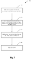
- FIG. 7 illustrates a deadlock victim selection and resolution process according to a further aspect.
- FIG. 8 illustrates an inference component that can facilitate selection of a node according to an aspect of the subject innovation.
- FIG. 9 is a schematic block diagram of a sample-computing environment that can be employed as part of resolving deadlocks in accordance with an aspect of the subject innovation.
- FIG. 10 illustrates an exemplary environment for implementing various aspects of the subject innovation.
- FIG. 1 illustrates a block diagram of a deadlock resolution system 100 that includes a graph transformation component 110 and a victim selection component 112 according to an aspect of the subject innovation.
- a deadlock is caused when two or more threads come into conflict over some resource, in such a way that no execution is possible.
- one common form of deadlock occurs when two or more threads wait for a resource that is owned by the other thread.
- the resolution system 100 resolves the deadlock by choosing one of the sessions as a deadlock victim, wherein such victim selection is based on cost and/or priority in a strongly connected component(s) 115 of a static wait-for graph 102 .
- An edge e from u to v is denoted by (u,v), and it is called an outgoing edge for u and an incoming edge for v.
- Node u can reach node v (or equivalently v is reachable from u) if there is a path from u to v in the graph.
- the notation uv is utilized to denote that v is reachable from u; and n is defined to be the number of vertices of a graph when this is clear from context.
- such graph 102 can represent wait-for relations among multiple units of execution (tasks) in a software process.
- V is the set of vertices, each of which represents a task
- E is the set of edges, each of which represents a wait-for relation between a pair of two tasks.
- each vertex can be associated with a cost given by the function C(v), representing the cost of selecting the corresponding task as a deadlock victim.
- wait-for-all there can exist two types of wait-for relations: wait-for-all and wait-for-any.
- the former represents a scenario in which the waiting task cannot make progress until all of its outgoing waits disappear.
- the latter represents a scenario in which the waiting task can make progress as soon as one of its outgoing waits disappears.
- the resolution system 100 can resolve all deadlocks captured by the wait-for graph efficiently in terms of deadlock resolution cost (sum of the cost of deadlock victim tasks).
- the deadlock resolution system 100 can identify deadlock cycles and analyze one or more data structures that store information concerning running threads, waiting threads to determine whether a deadlock exists.
- the resolution system 100 is further operable to perform one or more methods that can be employed to resolve a deadlock, providing advantages over conventional systems.
- the graph transformation component 110 manipulates the wait-for graph 102 such that by end of its processing, the remaining vertices/edges are in deadlocks, and the SCC(s) are hence computed. Put differently, the graph transformation component 110 reduces the wait-for graph, wherein by reducing the wait-for graph, the subgraphs that do not participate in the deadlocks are removed.
- the victim selection component 112 can traverse a wait for graph or strongly connected component and/or add and/or remove arcs and/or nodes therefrom to facilitate resolving a deadlock, by selecting a node candidate for abortion (e.g., a victim selection based on cost and/or priority), in a strongly connected component(s).
- a strongly connected component 115 represents a subgraph, wherein there exists a path from each vertex in the subgraph to every other vertex.
- the strongly connected components—SCC—of a directed graph represents its maximal strongly connected sub-graphs.
- FIG. 2 illustrates a graph transformation component 210 that further includes a graph reduction component 212 that reduces a generated wait-for graphs and a strongly connected component (SCC) computation unit 214 , which computes strongly connected components.
- SCC strongly connected component
- the victim selection depends on two procedures namely: graph reduction via the reduction component 212 and strongly connected component computation 214 , via the SCC computation unit.
- Graph reduction is an iterative procedure, wherein each iteration attempts to remove vertices and edges from the graph that definitely cannot participate in deadlock. The iteration continues until no additional vertices or edges can be removed from the graph, and hence the graph becomes stable.
- Such strongly-connected component computation is based on well-know algorithm.
- aspects of the subject innovation address how SCCs are employed in cost estimation, wherein one can compute strongly-connected components only once per wait-for graph. It can be assumed that subsequent graph reductions can only remove vertices from existing strongly-connected components, and not to split any one strongly-connected component into multiple strongly-connected components. Such is practical because one rarely observes wait-for graphs in which the number of edges greatly exceeds the number of vertices.
- the victim selection algorithm is essentially a cost-based greedy algorithm. In each victim selection iteration, the system 200 attempts to select a single optimal victim based on estimated remaining cost. The estimated remaining cost for selecting a particular vertex, v i , as the next deadlock victim can be represented as C(v i ) plus the estimated cost of resolving remaining deadlocks after removing v i from the wait-for graph.
- removing v i from the wait-for graph requires graph reduction, in case the removal of v i unblocks other vertices.
- changes to the wait-for graph can be considered transient and temporary (including graph reduction).
- the estimated cost for resolving all remaining deadlocks is simply the sum of the costs of the lowest-cost vertex in each remaining strongly-connected component.
- the above estimation is performed for each remaining vertex, and the vertex with the lowest estimated cost is chosen as the next deadlock victim.
- a vertex is confirmed to be the next deadlock victim, it is permanently removed from the wait-for graph, and the graph is then reduced permanently. Such process continues until the wait-for graph is empty (does not contain any deadlock).
- each vertex has a complex cost function, wherein the cost of a vertex depends on both the priority and the amount of log used by the associated task. Moreover, priority has precedence over log used, and the implementation groups potential deadlock victim vertices by priority, and in each victim selection iteration, only the group of vertices with the lowest priority.
- SQL Structured Query Language
- FIG. 3 illustrates a particular resolution of a cyclical deadlock based on cost calculation for a strongly connected component according to an aspect of the subject innovation.
- Victim selection is based on cost estimation units, wherein each strongly connected component has a unit of cost associated therewith.
- the total minimum cost to resolve all deadlocks and hence eliminate the strongly connected components in the graph can be determined.
- Such can be performed by obtaining optimal result via an approximation and hence not mitigating a requirement of iterating through scenarios of selecting all nodes and computing the associated costs.
- the system 300 presents a strongly connected component, wherein for such particular scenario it can be assumed that the priority remains the same for all three tasks, and hence deadlocks can be resolved based on minimum costs.
- the level of cost is T 1 , T 3 , T 2 , (“7” units, “8” units, “10” units) and the cost of the strongly component 300 (T 1 , T 2 , T 3 ) is the cost of the task with minimum cost in such component and hence “7”.
- T 1 can be assumed to be the victim, and upon aborting such task, tasks T 2 and T 3 will remain.
- the next task in the sorted list is T 3 , based on cost estimation.
- the final estimation is for aborting T 2 (having a cost of “10”) plus cost of the remaining strongly connected component (T 1 and T 3 ; which is zero, since such graph becomes empty after this reduction.) After removing T 2 both loops are removed and hence no strongly connected component exists, thus providing the least amount of cost as “10”. According, the victim selected is T 2 .
- FIG. 4 illustrates a related methodology 400 of selecting a node candidate for abortion in a wait-for graph based on a strongly connected component according to an aspect of the subject innovation. While the exemplary method is illustrated and described herein as a series of blocks representative of various events and/or acts, the subject innovation is not limited by the illustrated ordering of such blocks. For instance, some acts or events may occur in different orders and/or concurrently with other acts or events, apart from the ordering illustrated herein, in accordance with the innovation. In addition, not all illustrated blocks, events or acts, may be required to implement a methodology in accordance with the subject innovation.
- wait-for graph is constructed having a plurality of subgraphs, which further includes subgraphs that are connected or disconnected. From such wait-for graph, subgraphs that are not in a deadlock loop are subsequently removed at 420 , and the loops that represent deadlocks remain. Subsequent to such graph reduction stage 420 , strongly connected components associated with the wait-for graphs are computed at 430 , wherein each strongly connected components represents a path from a vertex to another vertex and backwards.
- each strongly connected component can act as a largest loop that contains the vertices (a vertex is associated with a cost, and deadlocks are broken based on an overall cost.)
- victim selection can be based on total cost of resolving all deadlocks in the wait-for graph at 440 .
- victim selection algorithm can be represented by a cost-based greedy algorithm, wherein in each victim selection iteration, a single optimal victim is selected based on estimated remaining cost (e.g., the unit of cost estimation is a strongly-connected component of the wait-for graph). As such, the victim can be removed and the cycle deadlock resolved.
- FIG. 5 illustrates a further methodology 500 of resolving deadlocks according to a further aspect.
- a “n-complex strongly-connected” component (where n is an integer) is defined, from which the removal of at most n vertices will yield sub-graphs that are no longer strongly connected.
- the strongly connected component can be examined as a whole, (as opposed to one deadlock cycle at a time), wherein victims can be selected based on estimated total cost at 530 (as opposed to detecting cycles in the graph or using cycles to select victims.)
- all deadlocks captured in the wait-for graph are examined simultaneously, wherein strongly-connected components in the wait-for graph are used as units for cost estimation. Accordingly, all deadlocks captured by the wait-for graph can be resolved efficiently (e.g., by mitigating permutation analysis) in terms of deadlock resolution cost, such as sum of the cost of the deadlock victim tasks.)
- FIG. 6 illustrates a related methodology 600 of deadlock resolution in accordance with an aspect of the subject innovation.
- the methodology 600 includes three phases namely; a graph reduction 610 , a computation stage of strongly connected components 620 and a victim selection stage 630 .
- the graph reduction stage 610 can further include a graph reduction iteration and verification of graph stability. If the graph reduction iteration performs any changes (e.g., removal of nodes and edges) to the wait-for graph reduction, such graph is considered unstable. From such wait-for graph, subgraphs that are not in a deadlock loop are subsequently removed, and hence the loops that represent deadlocks remain.
- the process 610 is iterated until the remaining vertices and edges are in deadlock.
- strongly connected components can be computed.
- Such strongly connected component represents a graph, wherein there exists a path from each vertex in the graph to every other vertex, and its maximal strongly connected sub-graphs.
- victim selection phase can be performed wherein such victim selection algorithm can be a cost-based greedy algorithm.
- a node having a cost of C(v i ) can then be selected at 632 and considered for abortion.
- Such node can then be assumed to be removed from the SCC at 634 and associated total cost can be estimated, namely cost of removal of selected node and the remaining nodes.
- the total cost can be represented by C(v i )+ ⁇ C(v j ), wherein, v j is the lowest-cost vertex in each remaining strongly-connected component.
- a single optimal victim is selected based on estimated remaining cost (e.g., the unit of cost estimation is a strongly-connected component of the wait-for graph).
- estimated remaining cost e.g., the unit of cost estimation is a strongly-connected component of the wait-for graph.
- the vertices in the Local Wait For Graph are sorted by priority (low to high) and log size (low to high), and then grouped by priority.
- the LWFG can consist of a set of vertices, a set of edges, and a set of SCCs.
- each vertex represents the tuple (search index, task progress mark), and each edge represents the wait-for relationship between two vertices.
- the grouping enforces the deadlock resolution policy that the resolution system should typically not abort a higher priority task while allowing a lower priority task to continue execution when both tasks are deadlock participants.
- An SCC's can be computed by first running graph reduction, and then removing reduced vertices and edges from the original SCC.
- Lowest costing vertex can be defined as a vertex with the lowest log size in the set of vertices that have the lowest priority.
- a simple SCC (e.g., a zero-complex) can be defined such that there is no sub-SCC in the sub-graph (SCC ⁇ v) for all v ⁇ SCC.
- a 1-complex SCC a SCC such that there are only simple sub-SCCs in the sub-graph (SCC ⁇ v) for all v ⁇ SCC.
- a n-complex (n ⁇ 2) SCC as a SCC such that there is at least one (n ⁇ 1)-complex sub-SCCs in the sub-graph (SCC ⁇ v) for all v ⁇ SCC.
- n log size of minimum cost v min in k-th sub-SCC
- n is the number of SCCs in the sub-graph (SCC ⁇ v), ⁇ v ⁇ SCC. Since each of the k sub-SCCs of (SCC ⁇ v) are at least 1-complex, and further applications of Kosaraju's algorithm are required to determine their sub-sub-SCCs, sub-sub-sub-SCCs, and so on, until all remaining SCCs are either simple or 1-complex, in order to determine the actual deadlock resolution cost. The runtime complexity of such a solution is too high to be practical. It is to be appreciated that the above discussion represents a particular scenario for applying heuristics and the subject innovation is not so limited.
- the subject innovation can further yield an efficient solution for deadlock victim set. It is to be appreciated that further aspects can constrain the design further to make the deadlock resolution strategy optimal for all 1-complex SCCs (without condition). Such typically requires the resolution system to use Kosaraju algorithm to compute the actual remaining SCCs after graph reduction for every cost estimation.
- FIG. 7 illustrates an exemplary methodology 700 that reduces a wait-for graph based on cost and priority.
- priority takes precedence over cost (e.g. log size) for costable deadlocks.
- cost e.g. log size
- the subject innovation can typically ensure that no higher priority task is selected as deadlock victim until all lower priority tasks are either chosen as deadlock victim or removed from the graph due to the selection of other victims.
- total cost of removal can be determined based on cost and priority, and graph reduced at 740 .
- FIG. 8 illustrates an inference component 810 that can facilitate victim selection in a strongly connected component(s) of a static wait-for graph, for resolving deadlock cycles.
- such can include supplying heuristics for cost estimation associated with victim selection.
- the term “inference” refers generally to the process of reasoning about or inferring states of the system, environment, and/or user from a set of observations as captured via events and/or data. Inference can be employed to identify a specific context or action, or can generate a probability distribution over states, for example.
- the inference can be probabilistic—that is, the computation of a probability distribution over states of interest based on a consideration of data and events.
- Inference can also refer to techniques employed for composing higher-level events from a set of events and/or data. Such inference results in the construction of new events or actions from a set of observed events and/or stored event data, whether or not the events are correlated in close temporal proximity, and whether the events and data come from one or several event and data sources.
- the inference component 810 can employ any of a variety of suitable AI-based schemes as described supra in connection with facilitating various aspects of the herein described invention.
- a process for learning explicitly or implicitly when to embed origination information in data records can be facilitated via an automatic classification system and process.
- Classification can employ a probabilistic and/or statistical-based analysis (e.g., factoring into the analysis utilities and costs) to prognose or infer an action that a user desires to be automatically performed.
- SVM support vector machine
- Other classification approaches include Bayesian networks, decision trees, and probabilistic classification models providing different patterns of independence can be employed.
- Classification as used herein also is inclusive of statistical regression that is utilized to develop models of priority.
- the subject innovation can employ classifiers that are explicitly trained (e.g., via a generic training data) as well as implicitly trained (e.g., via observing user behavior, receiving extrinsic information) so that the classifier is used to automatically determine according to a predetermined criteria which answer to return to a question.
- SVM's that are well understood, SVM's are configured via a learning or training phase within a classifier constructor and feature selection module.
- a component can be, but is not limited to being, a process running on a processor, a processor, an object, an instance, an executable, a thread of execution, a program and/or a computer.
- an application running on a computer and the computer can be a component.
- One or more components may reside within a process and/or thread of execution and a component may be localized on one computer and/or distributed between two or more computers.
- exemplary is used herein to mean serving as an example, instance or illustration. Any aspect or design described herein as “exemplary” is not necessarily to be construed as preferred or advantageous over other aspects or designs. Similarly, examples are provided herein solely for purposes of clarity and understanding and are not meant to limit the subject innovation or portion thereof in any manner. It is to be appreciated that a myriad of additional or alternate examples could have been presented, but have been omitted for purposes of brevity.
- computer readable media can include but are not limited to magnetic storage devices (e.g., hard disk, floppy disk, magnetic strips . . . ), optical disks (e.g., compact disk (CD), digital versatile disk (DVD) . . . ), smart cards, and flash memory devices (e.g., card, stick, key drive . . . ).
- magnetic storage devices e.g., hard disk, floppy disk, magnetic strips . . .
- optical disks e.g., compact disk (CD), digital versatile disk (DVD) . . .
- smart cards e.g., card, stick, key drive . . .
- a carrier wave can be employed to carry computer-readable electronic data such as those used in transmitting and receiving electronic mail or in accessing a network such as the Internet or a local area network (LAN).
- LAN local area network
- FIGS. 9 and 10 are intended to provide a brief, general description of a suitable environment in which the various aspects of the disclosed subject matter may be implemented. While the subject matter has been described above in the general context of computer-executable instructions of a computer program that runs on a computer and/or computers, those skilled in the art will recognize that the innovation also may be implemented in combination with other program modules. Generally, program modules include routines, programs, components, data structures, and the like, which perform particular tasks and/or implement particular abstract data types.
- an exemplary environment 910 for implementing various aspects of the subject innovation includes a computer 912 .
- the computer 912 includes a processing unit 914 , a system memory 916 , and a system bus 918 .
- the system bus 918 couples system components including, but not limited to, the system memory 916 to the processing unit 914 .
- the processing unit 914 can be any of various available processors. Dual microprocessors and other multiprocessor architectures also can be employed as the processing unit 914 .
- the system bus 918 can be any of several types of bus structure(s) including the memory bus or memory controller, a peripheral bus or external bus, and/or a local bus using any variety of available bus architectures including, but not limited to, 11-bit bus, Industrial Standard Architecture (ISA), Micro-Channel Architecture (MSA), Extended ISA (EISA), Intelligent Drive Electronics (IDE), VESA Local Bus (VLB), Peripheral Component Interconnect (PCI), Universal Serial Bus (USB), Advanced Graphics Port (AGP), Personal Computer Memory Card International Association bus (PCMCIA), and Small Computer Systems Interface (SCSI).
- ISA Industrial Standard Architecture
- MSA Micro-Channel Architecture
- EISA Extended ISA
- IDE Intelligent Drive Electronics
- VLB VESA Local Bus
- PCI Peripheral Component Interconnect
- USB Universal Serial Bus
- AGP Advanced Graphics Port
- PCMCIA Personal Computer Memory Card International Association bus
- SCSI Small Computer Systems Interface
- the system memory 916 includes volatile memory 920 and nonvolatile memory 922 .
- the basic input/output system (BIOS) containing the basic routines to transfer information between elements within the computer 912 , such as during start-up, is stored in nonvolatile memory 922 .
- nonvolatile memory 922 can include read only memory (ROM), programmable ROM (PROM), electrically programmable ROM (EPROM), electrically erasable ROM (EEPROM), or flash memory.
- Volatile memory 920 includes random access memory (RAM), which acts as external cache memory.
- RAM is available in many forms such as synchronous RAM (SRAM), dynamic RAM (DRAM), synchronous DRAM (SDRAM), double data rate SDRAM (DDR SDRAM), enhanced SDRAM (ESDRAM), Synchlink DRAM (SLDRAM), and direct Rambus RAM (DRRAM).
- SRAM synchronous RAM
- DRAM dynamic RAM
- SDRAM synchronous DRAM
- DDR SDRAM double data rate SDRAM
- ESDRAM enhanced SDRAM
- SLDRAM Synchlink DRAM
- DRRAM direct Rambus RAM
- Computer 912 also includes removable/non-removable, volatile/nonvolatile computer storage media.
- FIG. 9 illustrates a disk storage 924 , wherein such disk storage 924 includes, but is not limited to, devices like a magnetic disk drive, floppy disk drive, tape drive, Jaz drive, Zip drive, LS-60 drive, flash memory card, or memory stick.
- disk storage 924 can include storage media separately or in combination with other storage media including, but not limited to, an optical disk drive such as a compact disk ROM device (CD-ROM), CD recordable drive (CD-R Drive), CD rewritable drive (CD-RW Drive) or a digital versatile disk ROM drive (DVD-ROM).
- CD-ROM compact disk ROM device
- CD-R Drive CD recordable drive
- CD-RW Drive CD rewritable drive
- DVD-ROM digital versatile disk ROM drive
- a removable or non-removable interface is typically used such as interface 926 .
- FIG. 9 describes software that acts as an intermediary between users and the basic computer resources described in suitable operating environment 910 .
- Such software includes an operating system 928 .
- Operating system 928 which can be stored on disk storage 924 , acts to control and allocate resources of the computer system 912 .
- System applications 930 take advantage of the management of resources by operating system 928 through program modules 932 and program data 934 stored either in system memory 916 or on disk storage 924 . It is to be appreciated that various components described herein can be implemented with various operating systems or combinations of operating systems.
- Input devices 936 include, but are not limited to, a pointing device such as a mouse, trackball, stylus, touch pad, keyboard, microphone, joystick, game pad, satellite dish, scanner, TV tuner card, digital camera, digital video camera, web camera, and the like. These and other input devices connect to the processing unit 914 through the system bus 918 via interface port(s) 938 .
- Interface port(s) 938 include, for example, a serial port, a parallel port, a game port, and a universal serial bus (USB).
- Output device(s) 940 use some of the same type of ports as input device(s) 936 .
- a USB port may be used to provide input to computer 912 , and to output information from computer 912 to an output device 940 .
- Output adapter 942 is provided to illustrate that there are some output devices 940 like monitors, speakers, and printers, among other output devices 940 that require special adapters.
- the output adapters 942 include, by way of illustration and not limitation, video and sound cards that provide a means of connection between the output device 940 and the system bus 918 . It should be noted that other devices and/or systems of devices provide both input and output capabilities such as remote computer(s) 944 .
- Computer 912 can operate in a networked environment using logical connections to one or more remote computers, such as remote computer(s) 944 .
- the remote computer(s) 944 can be a personal computer, a server, a router, a network PC, a workstation, a microprocessor based appliance, a peer device or other common network node and the like, and typically includes many or all of the elements described relative to computer 912 .
- only a memory storage device 946 is illustrated with remote computer(s) 944 .
- Remote computer(s) 944 is logically connected to computer 912 through a network interface 948 and then physically connected via communication connection 950 .
- Network interface 948 encompasses communication networks such as local-area networks (LAN) and wide-area networks (WAN).
- LAN technologies include Fiber Distributed Data Interface (FDDI), Copper Distributed Data Interface (CDDI), Ethernet/IEEE 802.3, Token Ring/IEEE 802.5 and the like.
- WAN technologies include, but are not limited to, point-to-point links, circuit switching networks like Integrated Services Digital Networks (ISDN) and variations thereon, packet switching networks, and Digital Subscriber Lines (DSL).
- ISDN Integrated Services Digital Networks
- DSL Digital Subscriber Lines
- Communication connection(s) 950 refers to the hardware/software employed to connect the network interface 948 to the bus 918 . While communication connection 950 is shown for illustrative clarity inside computer 912 , it can also be external to computer 912 .
- the hardware/software necessary for connection to the network interface 948 includes, for exemplary purposes only, internal and external technologies such as, modems including regular telephone grade modems, cable modems and DSL modems, ISDN adapters, and Ethernet cards.
- FIG. 10 is a schematic block diagram of a sample-computing environment 1000 that can be employed as part of resolving deadlocks in accordance with an aspect of the subject innovation.
- the system 1000 includes one or more client(s) 1010 .
- the client(s) 1010 can be hardware and/or software (e.g., threads, processes, computing devices).
- the system 1000 also includes one or more server(s) 1030 .
- the server(s) 1030 can also be hardware and/or software (e.g., threads, processes, computing devices).
- the servers 1030 can house threads to perform transformations by employing the components described herein, for example.
- One possible communication between a client 1010 and a server 1030 may be in the form of a data packet adapted to be transmitted between two or more computer processes.
- the system 1000 includes a communication framework 1050 that can be employed to facilitate communications between the client(s) 1010 and the server(s) 1030 .
- the client(s) 1010 are operatively connected to one or more client data store(s) 1060 that can be employed to store information local to the client(s) 1010 .
- the server(s) 1030 are operatively connected to one or more server data store(s) 1040 that can be employed to store information local to the servers 1030 .
Abstract
Description
-
- Actual cost of resolving all deadlocks in a simple SCC if v is selected as a victim=log size of v, ∀vεSCC.
- Actual cost of resolving all deadlocks in a 1-complex SCC if v is selected as a victim=log size of v+Σk−1 . . . n(cost of resolving all deadlocks in k-th sub-SCC)=log size of v+Σk=1 . . . n(log size of minimum cost vmin k-th sub-SCC), where n is the number of SCCs in the sub-graph (SCC−v), ∀vεSCC.
Claims (20)
Priority Applications (1)
| Application Number | Priority Date | Filing Date | Title |
|---|---|---|---|
| US12/272,312 US9104989B2 (en) | 2008-11-17 | 2008-11-17 | Priority and cost based deadlock victim selection via static wait-for graph |
Applications Claiming Priority (1)
| Application Number | Priority Date | Filing Date | Title |
|---|---|---|---|
| US12/272,312 US9104989B2 (en) | 2008-11-17 | 2008-11-17 | Priority and cost based deadlock victim selection via static wait-for graph |
Publications (2)
| Publication Number | Publication Date |
|---|---|
| US20100125480A1 US20100125480A1 (en) | 2010-05-20 |
| US9104989B2 true US9104989B2 (en) | 2015-08-11 |
Family
ID=42172710
Family Applications (1)
| Application Number | Title | Priority Date | Filing Date |
|---|---|---|---|
| US12/272,312 Expired - Fee Related US9104989B2 (en) | 2008-11-17 | 2008-11-17 | Priority and cost based deadlock victim selection via static wait-for graph |
Country Status (1)
| Country | Link |
|---|---|
| US (1) | US9104989B2 (en) |
Families Citing this family (2)
| Publication number | Priority date | Publication date | Assignee | Title |
|---|---|---|---|---|
| US10635653B2 (en) * | 2016-04-20 | 2020-04-28 | Unisys Corporation | Systems and methods for implementing a multi-host record lock deadlock feedback mechanism |
| CN108762201B (en) * | 2018-04-18 | 2021-02-09 | 南京工业大学 | Pearson correlation-based large system graph theory decomposition method |
Citations (21)
| Publication number | Priority date | Publication date | Assignee | Title |
|---|---|---|---|---|
| US5459871A (en) * | 1992-10-24 | 1995-10-17 | International Computers Limited | Detection and resolution of resource deadlocks in a distributed data processing system |
| US5664088A (en) | 1995-09-12 | 1997-09-02 | Lucent Technologies Inc. | Method for deadlock recovery using consistent global checkpoints |
| US5682537A (en) * | 1995-08-31 | 1997-10-28 | Unisys Corporation | Object lock management system with improved local lock management and global deadlock detection in a parallel data processing system |
| US5764976A (en) | 1995-02-06 | 1998-06-09 | International Business Machines Corporation | Method and system of deadlock detection in a data processing system having transactions with multiple processes capable of resource locking |
| US5835766A (en) | 1994-11-04 | 1998-11-10 | Fujitsu Limited | System for detecting global deadlocks using wait-for graphs and identifiers of transactions related to the deadlocks in a distributed transaction processing system and a method of use therefore |
| US5961599A (en) * | 1996-10-15 | 1999-10-05 | Lucent Technologies Inc. | Apparatus and method for computing the processing delay of adaptive applications network terminals and applications thereof |
| US6223200B1 (en) * | 1989-12-22 | 2001-04-24 | International Business Machines Corporation | System and method for reducing research time through a lock wait matrix |
| US6304938B1 (en) | 1999-02-23 | 2001-10-16 | Oracle Corporation | Detecting a state change in a lock structure to validate a potential deadlock |
| US6336204B1 (en) * | 1998-05-07 | 2002-01-01 | Applied Materials, Inc. | Method and apparatus for handling deadlocks in multiple chamber cluster tools |
| US20030028638A1 (en) * | 2001-08-03 | 2003-02-06 | Srivastava Alok Kumar | Victim selection for deadlock detection |
| US20040068501A1 (en) * | 2002-10-03 | 2004-04-08 | Mcgoveran David O. | Adaptive transaction manager for complex transactions and business process |
| US6807540B2 (en) * | 2000-10-06 | 2004-10-19 | International Business Machines Corporation | System and method for deadlock management in database systems with demultiplexed connections |
| US20050091025A1 (en) * | 2003-08-26 | 2005-04-28 | Wilson James C. | Methods and systems for improved integrated circuit functional simulation |
| US20050138200A1 (en) * | 2003-12-17 | 2005-06-23 | Palo Alto Research Center, Incorporated | Information driven routing in ad hoc sensor networks |
| US20070106667A1 (en) * | 2005-11-10 | 2007-05-10 | Microsoft Corporation | Generalized deadlock resolution in databases |
| US20070294217A1 (en) * | 2006-06-14 | 2007-12-20 | Nec Laboratories America, Inc. | Safety guarantee of continuous join queries over punctuated data streams |
| US7355975B2 (en) * | 2004-04-30 | 2008-04-08 | International Business Machines Corporation | Method and apparatus for group communication with end-to-end reliability |
| US20080282244A1 (en) * | 2007-05-07 | 2008-11-13 | Microsoft Corporation | Distributed transactional deadlock detection |
| US7783610B2 (en) * | 2004-11-01 | 2010-08-24 | Sybase, Inc. | Distributed database system providing data and space management methodology |
| US7783806B2 (en) * | 2008-03-17 | 2010-08-24 | International Business Machines Corporation | Deadlock prevention in a computing environment |
| US7929460B2 (en) * | 2006-09-14 | 2011-04-19 | Vanu, Inc. | Communication network topology determination |
-
2008
- 2008-11-17 US US12/272,312 patent/US9104989B2/en not_active Expired - Fee Related
Patent Citations (22)
| Publication number | Priority date | Publication date | Assignee | Title |
|---|---|---|---|---|
| US6223200B1 (en) * | 1989-12-22 | 2001-04-24 | International Business Machines Corporation | System and method for reducing research time through a lock wait matrix |
| US5459871A (en) * | 1992-10-24 | 1995-10-17 | International Computers Limited | Detection and resolution of resource deadlocks in a distributed data processing system |
| US5835766A (en) | 1994-11-04 | 1998-11-10 | Fujitsu Limited | System for detecting global deadlocks using wait-for graphs and identifiers of transactions related to the deadlocks in a distributed transaction processing system and a method of use therefore |
| US5764976A (en) | 1995-02-06 | 1998-06-09 | International Business Machines Corporation | Method and system of deadlock detection in a data processing system having transactions with multiple processes capable of resource locking |
| US5682537A (en) * | 1995-08-31 | 1997-10-28 | Unisys Corporation | Object lock management system with improved local lock management and global deadlock detection in a parallel data processing system |
| US5664088A (en) | 1995-09-12 | 1997-09-02 | Lucent Technologies Inc. | Method for deadlock recovery using consistent global checkpoints |
| US5961599A (en) * | 1996-10-15 | 1999-10-05 | Lucent Technologies Inc. | Apparatus and method for computing the processing delay of adaptive applications network terminals and applications thereof |
| US6336204B1 (en) * | 1998-05-07 | 2002-01-01 | Applied Materials, Inc. | Method and apparatus for handling deadlocks in multiple chamber cluster tools |
| US6304938B1 (en) | 1999-02-23 | 2001-10-16 | Oracle Corporation | Detecting a state change in a lock structure to validate a potential deadlock |
| US6807540B2 (en) * | 2000-10-06 | 2004-10-19 | International Business Machines Corporation | System and method for deadlock management in database systems with demultiplexed connections |
| US7185339B2 (en) * | 2001-08-03 | 2007-02-27 | Oracle International Corporation | Victim selection for deadlock detection |
| US20030028638A1 (en) * | 2001-08-03 | 2003-02-06 | Srivastava Alok Kumar | Victim selection for deadlock detection |
| US20040068501A1 (en) * | 2002-10-03 | 2004-04-08 | Mcgoveran David O. | Adaptive transaction manager for complex transactions and business process |
| US20050091025A1 (en) * | 2003-08-26 | 2005-04-28 | Wilson James C. | Methods and systems for improved integrated circuit functional simulation |
| US20050138200A1 (en) * | 2003-12-17 | 2005-06-23 | Palo Alto Research Center, Incorporated | Information driven routing in ad hoc sensor networks |
| US7355975B2 (en) * | 2004-04-30 | 2008-04-08 | International Business Machines Corporation | Method and apparatus for group communication with end-to-end reliability |
| US7783610B2 (en) * | 2004-11-01 | 2010-08-24 | Sybase, Inc. | Distributed database system providing data and space management methodology |
| US20070106667A1 (en) * | 2005-11-10 | 2007-05-10 | Microsoft Corporation | Generalized deadlock resolution in databases |
| US20070294217A1 (en) * | 2006-06-14 | 2007-12-20 | Nec Laboratories America, Inc. | Safety guarantee of continuous join queries over punctuated data streams |
| US7929460B2 (en) * | 2006-09-14 | 2011-04-19 | Vanu, Inc. | Communication network topology determination |
| US20080282244A1 (en) * | 2007-05-07 | 2008-11-13 | Microsoft Corporation | Distributed transactional deadlock detection |
| US7783806B2 (en) * | 2008-03-17 | 2010-08-24 | International Business Machines Corporation | Deadlock prevention in a computing environment |
Non-Patent Citations (17)
| Title |
|---|
| "A Distributed Algorithm for Detecting Resource Deadlocks in Distributed Systems", by K. M. Chandy and J. Misra, Computer Sciences, University of Texan at Austin; 1982. * |
| "A Performance Study of Deadlock Resolution in Distributed System", by Chidori Kawamura Boeheim, Ph.D. University of Illinois at Urbana-Champaign, 1991. * |
| "Deadlock Detection in Distributed Databases", by Edgar Knapp, Department of Computer Sciences, University of Texas at Austin; ACM Computing Surveys, vol. 19, No. 4, Dec. 1987. * |
| "Deadlock Detection in Distributed Object Systems", Nima Kaveh and Wolfgang Emmerich, Department of Computer Science, University College London, Gower Street, London WC1 E 6BT, UK, http://www.cs.ucl.ac.uk/staff/w.emmerich/publications/ESEC01/ModelChecking/index.html; Aug. 8, 2001. * |
| "Deadlock Resolution and Semantic Lock Models in OO Distributed Systems", by Marina Roesler and Walter A. Burkhard, Department of Computer Science and Engineering. University of California, San Diego, La Jolla, CA 92093; 1998. * |
| "Efficient Deadlock Resolution for Lock-Based Concurrency Control Schemes", by Roesler et al., Department of Computer Science and Engineering, University of California, San Diego. IEEE 1988. * |
| "Just-in-Time and Just-in-Place Deadlock Resolution", by Fancong Zeng, Graduate Program in Computer Sciences, University of New Jersey; May 2007. * |
| "Locking and Deadlock Detection in Distributed Databases", by Daniel A. Menasce and Richard R. Muntz, IEEE Transactions on Software Engineering, vol. SE-5, No. 3, May 1979. * |
| "Stochastic Analysis of Distributed Deadlock Scheduling", by Shigang Chen and Yibei Ling, Department of Computer & Information Science & Engineering. University of Florida; PODC' 05, Jul. 17-20, 2005, Las Vegas, Nevada, USA. * |
| CIS 307: Deadlocks. http://www.cis.temple.edu/~ingargio/cis307/readings/deadlock.html. Last accessed Sep. 11, 2008, 8 pages. |
| CIS 307: Deadlocks. http://www.cis.temple.edu/˜ingargio/cis307/readings/deadlock.html. Last accessed Sep. 11, 2008, 8 pages. |
| Lee, et al. A Distributed Algorithm for Deadlock Detection under OR-request Model. http://ieeexplore.ieee.org/iel5/6512/17396/00805109.pdf?tp=&isnumber=&arnumber=805109, 2 pages, last accessed Sep. 11, 2008. |
| Prabhakaran. Distributed Deadlock Detection. http://www.utdallas.edu/~praba/aos-7-s04.ppt. Last accessed Sep. 11, 2008, 24 pages. |
| Prabhakaran. Distributed Deadlock Detection. http://www.utdallas.edu/˜praba/aos-7-s04.ppt. Last accessed Sep. 11, 2008, 24 pages. |
| Shkapenyuk, et al. Deadlock Resolution in Pipelined Query Graphs. Mar. 2005. http://nms.csail.mit.edu/~stavros/pubs/deadlock.pdf, 16 pages. |
| Shkapenyuk, et al. Deadlock Resolution in Pipelined Query Graphs. Mar. 2005. http://nms.csail.mit.edu/˜stavros/pubs/deadlock.pdf, 16 pages. |
| Soojung Lee, "Fast, Centralized Detection and Resolution of Distributed Deadlocks in Generalized Model", IEEE Transactions on Software Engineering, vol. 30, No. 9, Sep. 2004. * |
Also Published As
| Publication number | Publication date |
|---|---|
| US20100125480A1 (en) | 2010-05-20 |
Similar Documents
| Publication | Publication Date | Title |
|---|---|---|
| CN108595157B (en) | Block chain data processing method, device, equipment and storage medium | |
| US8104030B2 (en) | Mechanism to restrict parallelization of loops | |
| US10824646B2 (en) | Linking single system synchronous inter-domain transaction activity | |
| US8087022B2 (en) | Prevention of deadlock in a distributed computing environment | |
| Galil et al. | Resolving message complexity of byzantine agreement and beyond | |
| CN104065636B (en) | Data processing method and system | |
| EP2567316A2 (en) | System and method for determining application dependency paths in a data center | |
| CN110233802B (en) | Method for constructing block chain structure with one main chain and multiple side chains | |
| CN110134385A (en) | Record the method and C language general journal frame of C language function call chain | |
| Diaz et al. | Pessimism in the stochastic analysis of real-time systems: Concept and applications | |
| CN110505228B (en) | Edge cloud architecture-based big data processing method, system, medium and device | |
| US8060878B2 (en) | Prevention of deadlock in a distributed computing environment | |
| CN106713396A (en) | Server scheduling method and system | |
| US20120131588A1 (en) | Apparatus and method for data processing in heterogeneous multi-processor environment | |
| US20070118652A1 (en) | Bundling and sending work units to a server based on a weighted cost | |
| CN108415757A (en) | distributed transaction processing method and device | |
| US9104989B2 (en) | Priority and cost based deadlock victim selection via static wait-for graph | |
| CN104346220A (en) | Task scheduling method and system | |
| CN108664322A (en) | Data processing method and system | |
| US10831590B2 (en) | Error handling | |
| CN106874215B (en) | Serialized storage optimization method based on Spark operator | |
| US11164348B1 (en) | Systems and methods for general-purpose temporal graph computing | |
| CN117009063A (en) | Task execution method and device | |
| Roesler et al. | Efficient deadlock resolution for lock-based concurrency control schemes | |
| CN116701091A (en) | Method, electronic device and computer program product for deriving logs |
Legal Events
| Date | Code | Title | Description |
|---|---|---|---|
| AS | Assignment |
Owner name: MICROSOFT CORPORATION,WASHINGTON Free format text: ASSIGNMENT OF ASSIGNORS INTEREST;ASSIGNORS:BAI, YUXI;VERBITSKI, ALEXANDRE OLEGOVICH;WU, MING-CHUAN;REEL/FRAME:021844/0992 Effective date: 20081117 Owner name: MICROSOFT CORPORATION, WASHINGTON Free format text: ASSIGNMENT OF ASSIGNORS INTEREST;ASSIGNORS:BAI, YUXI;VERBITSKI, ALEXANDRE OLEGOVICH;WU, MING-CHUAN;REEL/FRAME:021844/0992 Effective date: 20081117 |
|
| AS | Assignment |
Owner name: MICROSOFT TECHNOLOGY LICENSING, LLC, WASHINGTON Free format text: ASSIGNMENT OF ASSIGNORS INTEREST;ASSIGNOR:MICROSOFT CORPORATION;REEL/FRAME:034564/0001 Effective date: 20141014 |
|
| ZAAA | Notice of allowance and fees due |
Free format text: ORIGINAL CODE: NOA |
|
| ZAAB | Notice of allowance mailed |
Free format text: ORIGINAL CODE: MN/=. |
|
| STCF | Information on status: patent grant |
Free format text: PATENTED CASE |
|
| MAFP | Maintenance fee payment |
Free format text: PAYMENT OF MAINTENANCE FEE, 4TH YEAR, LARGE ENTITY (ORIGINAL EVENT CODE: M1551); ENTITY STATUS OF PATENT OWNER: LARGE ENTITY Year of fee payment: 4 |
|
| FEPP | Fee payment procedure |
Free format text: MAINTENANCE FEE REMINDER MAILED (ORIGINAL EVENT CODE: REM.); ENTITY STATUS OF PATENT OWNER: LARGE ENTITY |
|
| LAPS | Lapse for failure to pay maintenance fees |
Free format text: PATENT EXPIRED FOR FAILURE TO PAY MAINTENANCE FEES (ORIGINAL EVENT CODE: EXP.); ENTITY STATUS OF PATENT OWNER: LARGE ENTITY |
|
| STCH | Information on status: patent discontinuation |
Free format text: PATENT EXPIRED DUE TO NONPAYMENT OF MAINTENANCE FEES UNDER 37 CFR 1.362 |
|
| FP | Lapsed due to failure to pay maintenance fee |
Effective date: 20230811 |